Enterprise architecture requires precision. When documenting complex systems, ambiguity leads to misalignment. ArchiMate provides a standardized language to visualize this complexity. This guide focuses on the three core viewpoints: Business, Application, and Technology. Understanding how to separate and connect these layers is essential for accurate modeling.
Many practitioners struggle with the initial step of diagramming. They often mix layers, creating diagrams that are difficult to read or validate. This tutorial breaks down the structural requirements for each viewpoint. It explains the semantics behind the symbols. The goal is clarity, not complexity.
🧩 Understanding the Core Structure
Before drawing a single shape, you must understand the underlying structure of the ArchiMate specification. The language is built upon three fundamental layers. These layers represent different concerns within an organization.
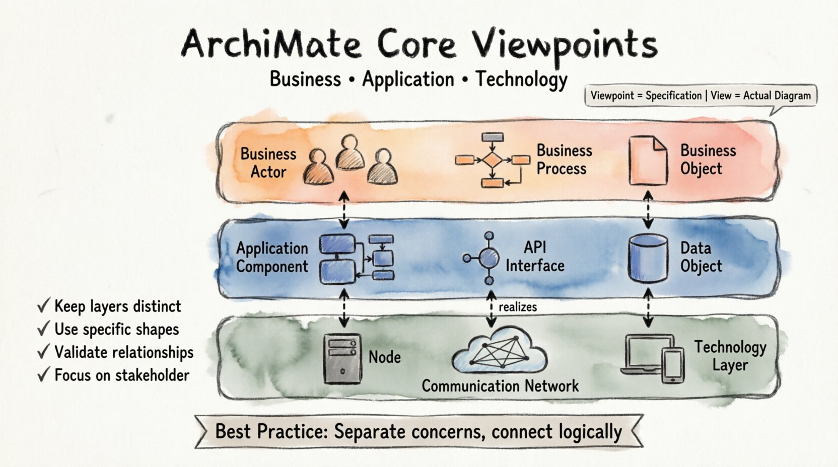
- Business Layer: Concerns the business strategy, governance, and operations. It describes what the organization does.
- Application Layer: Concerns the software applications that support the business processes. It describes how the business is supported digitally.
- Technology Layer: Concerns the physical and logical infrastructure. It describes where the applications run.
These layers are not isolated. They interact through specific relationships. However, a single diagram should not mix all elements indiscriminately. This is where the concept of a Viewpoint becomes critical.
Viewpoint vs. View
It is vital to distinguish between a Viewpoint and a View.
- Viewpoint: A specification of a model or diagram. It defines which elements and relationships are relevant for a specific stakeholder or concern.
- View: The actual diagram or representation created based on a Viewpoint.
When you draw a diagram, you are creating a View. You must select the appropriate Viewpoint to ensure the content is relevant to the audience. The three core Viewpoints align directly with the three layers.
🏢 The Business Viewpoint
The Business Viewpoint focuses on the organization’s operational reality. It abstracts away the digital and physical details to show how value is created. This diagram is typically read by managers, business analysts, and operational leads.
Key Elements in the Business Viewpoint
To draw a correct Business Viewpoint diagram, you must use elements from the Business Layer. Using elements from other layers here creates confusion.
- Business Actor: An entity that performs activities (e.g., a Customer, a Bank, an Employee).
- Business Role: A part of a business actor that performs a specific function (e.g., Accountant, Sales Rep).
- Business Process: A collection of activities that produces a specific result (e.g., Order Processing, Invoice Generation).
- Business Function: A capability required to accomplish a goal (e.g., Financial Management).
- Business Object: A thing of value to the business (e.g., Invoice, Product, Order).
- Business Event: Something that happens in time and triggers an activity (e.g., Order Received, Payment Due).
Key Relationships in the Business Viewpoint
Relationships define the logic of the diagram. In the Business Viewpoint, the most common relationships include:
- Association: A generic link between two elements. Use this when the relationship is structural.
- Flow: Indicates the flow of data or materials between processes or objects.
- Access: Indicates that a role or process accesses or uses an object.
- Serves: Indicates that a business function or process supports another business function or process.
- Realization: Indicates that a process realizes a function, or a function realizes a requirement.
Example Scenario: Order Management
Consider a scenario where a customer places an order. In the Business Viewpoint, you would model:
- A Business Actor representing the Customer.
- A Business Role representing the Sales Department.
- A Business Process named “Process Order”.
- A Business Object named “Sales Order”.
The Customer accesses the Sales Role. The Sales Role triggers the Process Order. The Process Order consumes the Sales Order object. This sequence describes the workflow without mentioning software or servers.
💻 The Application Viewpoint
The Application Viewpoint describes the logical software components that support the business. It is the bridge between business requirements and technical implementation. This diagram is typically read by solution architects and application developers.
Key Elements in the Application Viewpoint
All elements must belong to the Application Layer. Avoid mixing Business or Technology elements here.
- Application Component: A modular part of a system that provides a set of functionality (e.g., CRM Module, Inventory Service).
- Application Interface: A point of interaction where an application component interacts with another component or actor.
- Application Service: A set of functionality provided by an application component.
- Data Object: A logical representation of data used by an application (e.g., Customer Record, Stock Level).
Key Relationships in the Application Viewpoint
The relationships here focus on data flow and service usage.
- Usage: Indicates that an application component or interface uses a service.
- Access: Indicates that an application component accesses or modifies a data object.
- Realization: Indicates that a service is realized by a component.
- Communication: Indicates a network connection or data exchange between components.
Example Scenario: Customer Data
Continuing the previous scenario, how is the data handled? In the Application Viewpoint:
- An Application Component named “Order Management System”.
- An Application Interface named “API Gateway”.
- A Data Object named “Customer Data”.
The “Order Management System” accesses “Customer Data”. The “API Gateway” provides an interface to the “Order Management System”. This defines the logical architecture of the software.
🖥️ The Technology Viewpoint
The Technology Viewpoint describes the physical or virtual infrastructure. It covers hardware, networks, and platform software. This diagram is typically read by infrastructure engineers and operations teams.
Key Elements in the Technology Viewpoint
All elements must belong to the Technology Layer. Do not include business actors here.
- Node: A computational resource where applications are deployed (e.g., Server, Cloud Instance).
- Device: A resource where an application runs (e.g., Laptop, Mobile Phone).
- System Software: Software that provides a platform for applications (e.g., Operating System, Database Management System).
- Communication Network: A set of devices and software that enables communication (e.g., LAN, Internet).
- Path: A route for data transmission over a network.
Key Relationships in the Technology Viewpoint
These relationships focus on deployment and connectivity.
- Deployment: Indicates that an application component is deployed on a node or device.
- Realization: Indicates that a system software realizes a node (less common, but valid).
- Communication: Indicates a connection between nodes or devices.
- Access: Indicates that a node accesses a communication network.
Example Scenario: Deployment
How does the “Order Management System” run? In the Technology Viewpoint:
- A Node named “Production Server”.
- A System Software named “Linux OS”.
- A Communication Network named “Corporate LAN”.
The “Production Server” is deployed on the “Corporate LAN”. The “Linux OS” runs on the “Production Server”. This defines the physical environment.
🔗 Cross-Layer Relationships
While diagrams should focus on a single layer, Enterprise Architecture is about the connections between them. You must understand how layers relate to each other using specific cross-layer relationships.
Comparison of Core Layers
| Layer | Primary Concern | Key Question | Example Element |
|---|---|---|---|
| Business | Value Creation | What do we do? | Business Process |
| Application | Functionality | How do we do it digitally? | Application Component |
| Technology | Infrastructure | Where do we do it? | Node / Device |
The Realization Relationship
This is the most important relationship for connecting layers. It indicates that one element provides the means to fulfill another element.
- Business Process is realized by an Application Component.
- Application Component is realized by a Node.
When drawing a layered diagram, you often use dotted lines to show realization across layers. This maintains the integrity of the individual views while showing the dependency.
The Assignment Relationship
This relationship assigns an actor to a role or a component to a node. It is used to show ownership or location.
- A Business Actor is assigned to a Business Role.
- An Application Component is assigned to a Node.
⚠️ Common Modeling Errors
Even experienced practitioners make mistakes when starting out. Identifying these errors early saves time and improves model quality.
1. Mixing Layers on a Single Diagram
A common error is placing a Business Process directly connected to a Node without an intermediate Application layer. While technically possible in a “Combined” view, it violates the principle of separation of concerns.
- Correction: Keep Business, Application, and Technology diagrams separate. Use cross-layer relationships only to link them logically.
2. Using Generic Shapes
Using a generic rectangle for everything makes the diagram ambiguous. ArchiMate defines specific shapes for specific element types.
- Correction: Use the hexagon for Business Processes. Use the cylinder for Data Objects. Use the server icon for Nodes. Adhere to the notation standard.
3. Ignoring the Direction of Relationships
Relationships often have a direction. For example, a Flow represents data moving from one place to another. A Deployment represents software moving onto hardware.
- Correction: Ensure arrows point in the logical direction of the dependency or flow. Reverse arrows can misrepresent the architecture.
4. Overcomplicating the Diagram
Attempting to show every single detail in one diagram makes it unreadable. A diagram should serve a specific purpose.
- Correction: Focus on the scope. If you are modeling a process, focus on the processes. Do not clutter with infrastructure details unless they impact the process directly.
🛠️ Step-by-Step Modeling Workflow
To draw your first diagram correctly, follow a structured workflow. This ensures consistency and reduces the risk of errors.
Step 1: Define the Scope
Identify the specific business capability or system you are modeling. Are you modeling the sales department? Or the payment processing system? Define the boundaries.
Step 2: Select the Viewpoint
Choose the primary viewpoint. Will this be a Business Viewpoint diagram? An Application Viewpoint diagram? Select the elements available in that layer.
Step 3: Identify Key Elements
List the core actors, processes, components, or nodes involved. Write them down before placing them on the canvas.
Step 4: Define Relationships
Determine how these elements interact. Are they flowing data? Is one deployed on another? Is one realizing another? Define these connections logically.
Step 5: Draw and Arrange
Place the elements on the canvas. Group related elements together. Use alignment and spacing to improve readability. Ensure the flow reads from left to right or top to bottom.
Step 6: Review and Validate
Check against the ArchiMate specification. Are the shapes correct? Are the relationships valid for the selected layers? Ask a peer to review the diagram.
✅ Ensuring Consistency
Consistency is key to a maintainable model. Inconsistent modeling leads to confusion and errors in downstream systems.
Naming Conventions
- Use consistent naming across all layers. For example, if a Business Process is named “Order Processing”, the supporting Application Component should be named “Order Processing System”.
- Avoid vague names like “System 1” or “Process A”.
Standardization of Relationships
- Define which relationship types are allowed for your project. Some organizations restrict the use of generic “Association” links in favor of specific links like “Serves” or “Realizes”.
- Document these rules in a style guide.
Version Control
- Keep track of changes to the diagrams. Architecture evolves over time. Ensure you know which version represents the current state.
🚀 Moving Forward
Mastering the three core viewpoints takes practice. Start with small diagrams. Focus on accuracy rather than speed. As you become comfortable with the elements, you can tackle more complex scenarios involving motivation views or strategy views.
Remember that ArchiMate is a language. Like any language, it requires grammar and vocabulary to communicate effectively. By respecting the separation of layers and using the correct relationships, you ensure your diagrams convey the intended message.
Summary of Best Practices
- ✅ Keep Business, Application, and Technology diagrams distinct.
- ✅ Use specific element shapes for specific layer types.
- ✅ Validate relationships against the layer definitions.
- ✅ Focus on the specific concern of the stakeholder.
- ✅ Avoid mixing layers in a single view unless necessary.
With these principles in mind, your ArchiMate diagrams will be clear, accurate, and valuable assets for your organization’s architecture practice.