In complex enterprise environments, the architecture of information is just as critical as the code that processes it. Data Flow Diagrams (DFD) serve as a foundational blueprint for understanding how information moves through a system. They map the flow of data from external entities, through processes, into data stores, and back again. However, creating a DFD that accurately reflects reality without introducing confusion or technical debt requires precision. Many organizations struggle with diagrams that look correct visually but fail logically during implementation.
When a Data Flow Diagram contains fundamental errors, the consequences ripple through the development lifecycle. Misunderstood data flows lead to security vulnerabilities, inefficient database schemas, and integration failures. This guide examines the specific pitfalls that derail DFD accuracy in large-scale projects and provides actionable strategies to maintain structural integrity. By adhering to rigorous modeling standards, teams can ensure that their architectural documentation remains a reliable source of truth.
Understanding the Core Components of a DFD 🧱
Before identifying mistakes, it is essential to establish what constitutes a valid Data Flow Diagram. A DFD is a graphical representation of the flow of data. It does not show control flow, time sequences, or loops in the traditional sense of programming logic. Instead, it focuses on the movement and transformation of data. Every diagram relies on four primary symbols, and deviations here often lead to the most common errors.
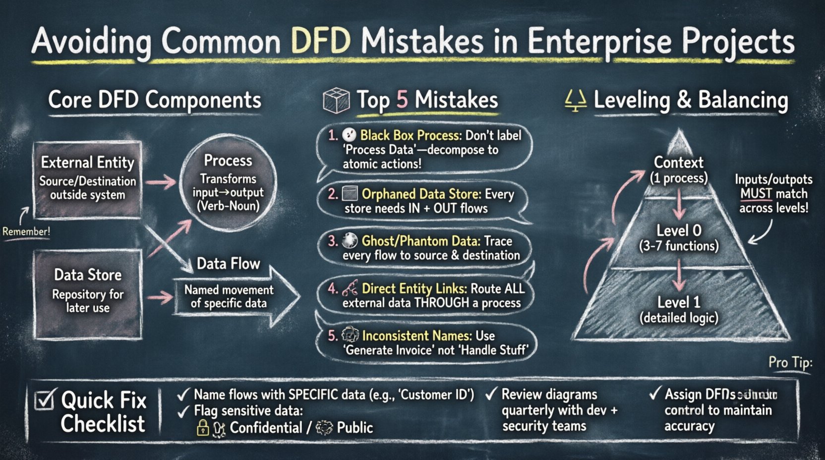
- External Entities: These represent sources or destinations of data outside the system boundary. They are usually people, organizations, or other systems. They initiate or receive data but do not store it within the current system context.
- Processes: These are actions that transform input data into output data. They must be functional; they cannot simply pass data through without modification unless explicitly modeling a pass-through operation. They are typically numbered to indicate hierarchy.
- Data Stores: These represent repositories where data is held for later use. Unlike processes, they do not change the data. They must be connected to processes via data flows.
- Data Flows: These are the arrows connecting the components. They represent the movement of data. Every flow must have a meaningful name describing the content being moved.
When these elements are misinterpreted, the diagram becomes ambiguous. For instance, connecting two external entities directly without a process implies that data bypasses the system logic, which is rarely the case in secure enterprise architectures. Understanding these definitions is the first step toward error-free modeling.
Top Data Flow Diagram Mistakes in Enterprise Contexts 🚨
Enterprise projects introduce layers of complexity that small-scale applications do not face. Multiple systems, legacy integrations, and strict security protocols mean that a simple diagram often hides significant risks. The following sections detail the most frequent modeling errors and their implications.
1. The Black Box Process Problem 🌑
A common issue arises when a process is labeled generically, such as “Process Data” or “Handle Request,” without defining the internal logic. While high-level diagrams (Context or Level 0) naturally summarize processes, lower-level diagrams (Level 1 and below) require decomposition. If a process is a “black box,” developers cannot determine what validation, transformation, or filtering occurs.
This mistake leads to:
- Unclear requirements for developers.
- Difficulty in identifying where business logic resides.
- Security blind spots where data might be exposed or mishandled.
To avoid this, ensure every process at Level 1 and below represents a distinct, atomic action. If a process is too large, decompose it into sub-processes until the logic is transparent.
2. Data Stores Without Data Flows 📦
Creating a data store symbol in a diagram but failing to connect it to any process is a critical error. A data store that receives no input data is useless. Conversely, a data store that has no outgoing flows implies data is trapped inside the system, never being used or reported.
This often happens when teams model a database schema first and then try to fit the DFD around it. The correct approach is to map the data movement first. If a table exists in the database but no business process reads or writes to it, it should be questioned. Is it an orphaned table? Is it a cache that needs a different modeling representation?
3. Ghost Flows and Phantom Data 👻
A “Ghost Flow” occurs when data is shown moving between two points but is never actually created or stored. For example, a flow might show “Customer ID” moving from an Entity to a Process, but the Entity does not provide that ID, nor does the Process generate it. This creates a contradiction in the logic.
Similarly, “Phantom Data” happens when a process outputs data that does not exist anywhere in the system. This often stems from copying diagrams from older projects where the data context was different. Every data flow must be traceable to a source and a destination.
4. Connecting External Entities Directly ⛓️
In a valid DFD, data must pass through a process to enter or leave the system boundary. Connecting two external entities directly implies that data bypasses the system entirely. While this might happen in real-world networking (e.g., API to API), in the context of system modeling, it suggests the system is not processing that interaction.
If two systems exchange data, there must be a process representing the interface, gateway, or service that handles the transmission. This distinction is vital for security auditing. If data flows directly, there is no opportunity for authentication, logging, or encryption within the modeled scope.
5. Inconsistent Naming Conventions 📝
Enterprise projects often involve multiple teams working on the same architecture documentation. Without strict naming conventions, one team might label a flow “User Login,” while another calls it “Authentication Request.” These semantic differences cause confusion during code reviews and testing.
A robust naming strategy requires:
- Noun-Verb Pairs: Processes should typically be named Verb-Noun (e.g., “Generate Report”).
- Data Names: Flows should be named with the specific data content (e.g., “Invoice Details” instead of “Data”).
- Consistency: The same term must be used for the same concept across all diagram levels.
Leveling and Balancing Errors ⚖️
Data Flow Diagrams are hierarchical. The Context Diagram shows the system as a single process. The Level 0 diagram breaks that process into major sub-processes. Level 1 diagrams further decompose Level 0 processes. A critical concept in this hierarchy is “balancing.”
Input and output flows must be consistent across levels. If a Level 0 process receives “Order Data” and “Customer Data,” the Level 1 diagrams that decompose that process must also receive “Order Data” and “Customer Data” at their inputs. You cannot introduce new inputs or outputs at a lower level without a corresponding change at the higher level.
Violating this rule creates a disconnect between the high-level overview and the detailed implementation. When a developer looks at a Level 1 diagram, they might find a data flow that was never mentioned in the Context Diagram, leading to scope creep or unimplemented features.
Table: DFD Level Comparison and Balancing
| Diagram Level | Focus | Process Count | Common Pitfall |
|---|---|---|---|
| Context Diagram | System Boundary | 1 | Too much detail or missing external entities |
| Level 0 (Top Level) | Major Functions | 3-7 | Inputs/Outputs do not match Context |
| Level 1 | Specific Logic | Decomposed | Imbalanced flows compared to parent process |
Security and Governance Implications 🔒
In enterprise settings, a DFD is not just a design tool; it is a security artifact. Flaws in the diagram often correlate to flaws in the security posture. When data flows are modeled incorrectly, access control lists (ACLs) are often misconfigured during development.
1. Unmodeled Data Sensitivity
If a data flow labeled “Employee Record” passes through a process that does not handle encryption, the diagram fails to highlight the risk. Enterprise standards often require that sensitive data be flagged. A DFD should ideally annotate flows with sensitivity levels (e.g., Public, Internal, Confidential). Ignoring this leads to compliance issues with regulations like GDPR or HIPAA.
2. Lack of Audit Trails
Every process that modifies data should ideally be traceable. If a DFD shows data moving from a Process to a Store without a clear identifier for the user or session, auditing becomes impossible. Teams often forget to model the “Session ID” or “Audit Token” flows that track who changed what and when.
3. Version Control for Diagrams
Unlike code, diagrams are often stored as static images or loose files. When a diagram changes, the version history is often lost. This results in developers working off outdated blueprints. A robust governance model treats DFDs as living documents stored in a version-controlled repository alongside the codebase.
Best Practices for Maintenance and Accuracy 🛠️
Even a perfectly drawn diagram can become obsolete quickly. Enterprise systems evolve. New integrations are added, and legacy components are retired. To maintain the utility of the DFD, teams must adopt specific maintenance practices.
- Integrate with Development: The diagram should be part of the definition of done. A feature is not complete until the DFD is updated to reflect the new data flows.
- Regular Reviews: Schedule quarterly reviews of the architecture documentation. Invite architects, developers, and security officers to validate the flows against the actual system behavior.
- Automate Where Possible: While manual modeling is common, some modeling tools allow for synchronization with code or configuration files. This reduces the chance of human error when updating the diagram.
- Clear Ownership: Assign a specific architect or technical lead as the owner of the DFD. Ambiguity about who updates the diagram leads to stagnation.
Table: Common Errors vs. Correct Approach
| Error Type | Why It Happens | Correct Approach |
|---|---|---|
| Missing Data Store | Assuming data passes through without saving | Identify persistence requirements for every process |
| Unbalanced Flows | Decomposing processes without tracking inputs | Ensure inputs/outputs match parent process exactly |
| Vague Labels | Using generic terms like “Info” or “Data” | Use specific data names (e.g., “Credit Card Number”) |
| Direct Entity Links | Ignoring system boundaries | Route all external data through a process |
Handling Legacy Systems and Integrations 🔄
One of the hardest challenges in enterprise DFD modeling is integrating legacy systems. Older systems often have undocumented data structures or proprietary protocols. When modeling these, teams often make assumptions that are incorrect.
For example, a legacy mainframe might send data in a fixed-width format that looks like one field but is actually three concatenated values. If the DFD models this as a single field, downstream developers will fail to parse it correctly. It is crucial to interview the owners of legacy systems and understand the actual data payload, not just the interface.
When modeling integrations:
- Map the Interface: Show the specific message format (e.g., XML, JSON, CSV) if relevant to the flow.
- Highlight Transformation: If the new system converts data to match the legacy system, model that transformation process explicitly.
- Document Constraints: If the legacy system has a data limit (e.g., 255 characters), note this on the data flow label.
The Role of Communication in Modeling 🗣️
Often, DFD errors stem from communication gaps between business analysts and technical teams. Business stakeholders describe the workflow in narrative terms, while developers think in logical structures. The DFD is the translation layer between these two groups.
If the diagram is too technical, business stakeholders cannot validate the logic. If it is too abstract, developers cannot build the solution. Finding the middle ground is essential. This involves using language that is precise but accessible. Avoid overly complex symbols that obscure the data movement.
Workshops are effective for resolving these discrepancies. Gather the team and walk through the diagram step-by-step. Ask questions like, “Where does this data come from?” and “What happens if this process fails?” These questions often reveal missing flows or unmodeled error states.
Conclusion on Rigor and Reliability ✅
Creating an accurate Data Flow Diagram is not about drawing lines; it is about defining the truth of how data moves through your organization. In enterprise projects, the cost of error is high. Security breaches, data loss, and rework are the direct results of flawed architecture documentation.
By avoiding the common mistakes outlined in this guide—such as ghost flows, unbalanced levels, and vague naming—teams can build a robust foundation for their systems. Treat the DFD as a living contract between the business requirements and the technical implementation. Regular reviews, strict governance, and clear communication ensure that the diagram remains a valuable asset throughout the project lifecycle.
Investing time in modeling correctly saves time in debugging later. A well-structured DFD clarifies scope, highlights security risks, and guides developers toward a consistent implementation. In the complex world of enterprise architecture, clarity is the most powerful tool available.