In the landscape of software development, understanding what a system must do is just as critical as understanding how it does it. Object-Oriented Analysis and Design (OOAD) relies heavily on capturing functional requirements through behavior. Use Case Modeling serves as the bridge between abstract user needs and concrete system specifications. This guide provides a structured approach to creating effective use cases without relying on specific tools or proprietary platforms.
Use Case Modeling is not merely about drawing diagrams. It is about defining the interactions between users and the system to achieve specific goals. By focusing on the narrative of usage, teams can identify gaps early, reduce rework, and ensure the final product aligns with business objectives. Let us explore the methodology required to build robust use case models.
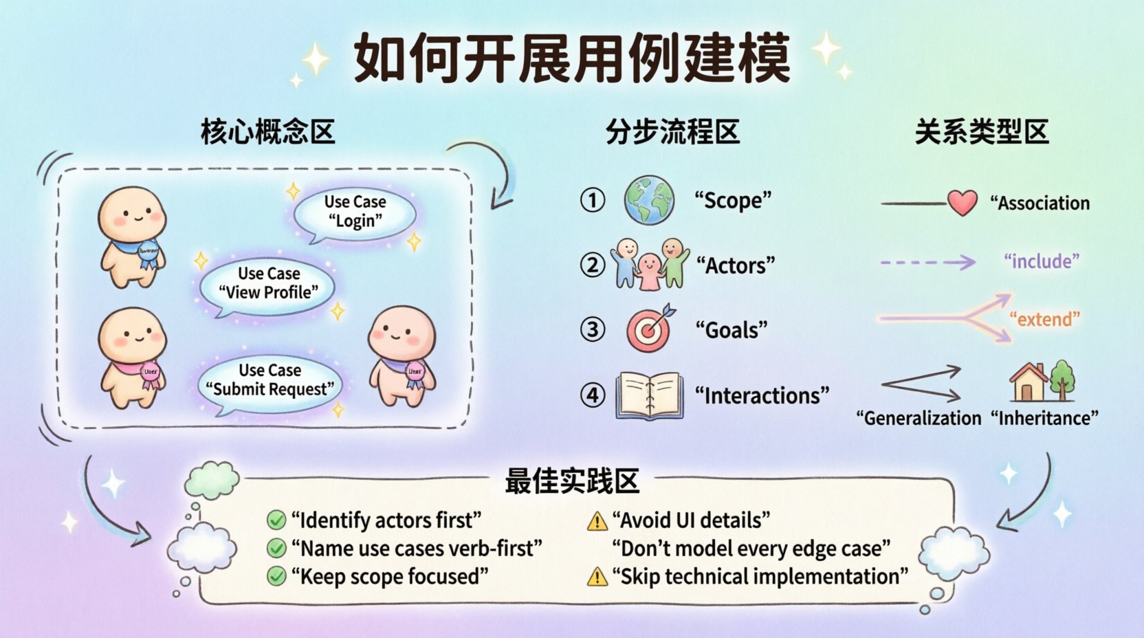
Understanding the Core Concepts 🧩
Before drawing lines and boxes, one must understand the building blocks. A use case model consists of several fundamental elements that work together to describe system behavior.
- Actors: Entities that interact with the system. They can be human users, other systems, or hardware devices. Actors are defined by the roles they play, not by specific individuals.
- Use Cases: Descriptions of sequences of actions that lead to a result of value to an actor. Each use case represents a specific goal.
- System Boundary: A clear line separating the system under consideration from the outside world. Everything inside is the system; everything outside is the environment.
- Relationships: Connections that define how actors and use cases interact, such as association, inclusion, extension, and generalization.
When approaching this task, remember that the goal is clarity. Ambiguity in modeling leads to ambiguity in implementation. Keep the scope focused and the language precise.
Step-by-Step Process 🛠️
Constructing a use case model is a phased activity. Rushing into diagramming without preparation often results in a scattered model that lacks coherence. Follow these sequential steps to ensure a solid foundation.
1. Define the System Scope 🌍
Start by answering the question: What is inside the box? Write a brief description of the system. Define what features are included in the current iteration and what is explicitly out of scope. This boundary helps prevent scope creep during the modeling phase.
- List the primary functions the system must perform.
- Identify the primary users or external systems that trigger these functions.
- Document the context in which the system operates.
2. Identify the Actors 👥
Actors are the drivers of the system. Identify everyone who interacts with the system, either directly or indirectly.
- Primary Actors: Those who initiate the use case to achieve their own goal. For example, a customer initiating a purchase.
- Secondary Actors: Those that assist the system but do not initiate the use case. For example, a payment gateway verifying funds.
- Internal Actors: Subsystems or components within the larger architecture that the current system interacts with.
Assign a clear name to each actor. Avoid using generic terms like “User.” Instead, use specific roles like “Administrator,” “Registered Member,” or “External Inventory System.”
3. Define Goals for Each Use Case 🎯
Every use case must have a name and a goal. The goal explains why the actor initiates the interaction. A good use case name is a verb-noun phrase, such as “Process Return” or “Generate Report.”
- Ensure the goal provides value to the actor.
- Ensure the goal is achievable within the system boundary.
- Avoid naming use cases based on system functions (e.g., “Click Button”) rather than goals (e.g., “Submit Application”).
4. Describe the Interactions 📝
Once the high-level diagram is sketched, detail the flow of events. This is often done using a Use Case Description document. This text-based specification complements the visual diagram.
For each use case, document the following:
- Preconditions: What must be true before the use case starts? (e.g., User is logged in).
- Postconditions: What is true after the use case completes successfully?
- Primary Flow: The standard path where everything goes as expected. Step-by-step interactions between actor and system.
- Alternative Flows: Variations of the primary flow, such as different user choices or system responses.
- Exception Flows: Error conditions or unexpected events that disrupt the normal flow.
Relationship Types 🔗
Use cases rarely exist in isolation. They relate to one another and to actors. Understanding these relationships helps reduce redundancy and clarifies system logic.
| Relationship | Symbol | Meaning | Example |
|---|---|---|---|
| Association | Line | An actor performs a use case. | A Customer performs “Place Order”. |
| Include | Dashed Line with <<include>> | One use case incorporates another behavior. | “Place Order” includes “Validate Payment”. |
| Extend | Dashed Line with <<extend>> | A use case adds behavior to another under specific conditions. | “View Cart” extends “Checkout” if cart is empty. |
| Generalization | Solid Line with Triangle | Inheritance of behavior between actors or use cases. | “Premium Customer” is a type of “Customer”. |
The Include Relationship
Use the Include relationship when a set of actions is needed by multiple use cases. This promotes reuse. If “Authenticate User” is required for “Login” and “Change Password,” it can be included in both. This ensures that if the authentication logic changes, you update it in one place.
The Extend Relationship
Use the Extend relationship for optional or conditional behavior. The extending use case adds functionality to the base use case only when a specific condition is met. This keeps the primary flow clean and readable.
The Generalization Relationship
This relationship represents an “is-a” relationship. For actors, it means a specialized actor inherits the capabilities of a general actor. For use cases, it means a specialized use case inherits the steps of a general use case but may add or override specific steps.
Best Practices for Documentation 📝
Creating a diagram is only half the work. The documentation must be detailed enough for developers to implement and testers to verify. Adhere to these standards to maintain quality.
- Keep it Atomic: Each use case should accomplish one distinct goal. If a use case is too complex, break it down into smaller, manageable sub-goals.
- Focus on Behavior: Do not describe the interface design, database schema, or specific algorithms in the use case description. Focus on the interaction and the state changes.
- Use Consistent Terminology: Ensure that terms used in the use case description match terms used in the domain model. This reduces confusion for stakeholders.
- Validate with Stakeholders: Review the use cases with actual users or business analysts. Ensure the goals match real-world expectations.
Common Pitfalls to Avoid ❌
Even experienced analysts can fall into traps that degrade the quality of the model. Be vigilant against these common errors.
- UI-Driven Modeling: Do not define use cases based on screen clicks or menu items. Use cases are about goals, not interfaces. If the user interface changes, the use case should remain valid.
- Over-Modeling: Do not model every possible minor variation. Focus on the significant flows that provide value. Minor details can be handled in the detailed design phase.
- Ignoring Non-Functional Requirements: While use cases focus on functionality, performance, security, and usability constraints often influence the flows. Document these constraints separately but acknowledge them.
- Vague Actors: Avoid actors like “System” unless it refers to a specific external subsystem. Ambiguous actor names lead to confusion about who is responsible for which action.
- Missing Exception Flows: Planning only for the happy path is a recipe for failure. Real-world usage involves errors, network failures, and invalid inputs. Document how the system handles these scenarios.
Refining the Model 🔄
Use Case Modeling is an iterative process. As understanding of the requirements deepens, the model must evolve. Regularly revisit the diagrams and descriptions to ensure they reflect the current understanding of the system.
During refinement, look for:
- Redundancies: Are there duplicate use cases that could be merged?
- Missing Flows: Are there actions actors need to perform that are not yet captured?
- Complexity: Are there use cases with too many steps that should be split?
- Clarity: Can a new developer read the description and understand the intent without asking questions?
Integration with Other Models 🧱
Use Case Modeling does not exist in a vacuum. It integrates with other models in the Object-Oriented Analysis and Design process.
- Class Diagrams: Use cases often reveal the classes and objects needed to support the behavior. If a use case involves “Calculate Tax,” there will likely be a “TaxCalculator” class.
- Sequence Diagrams: For complex use cases, sequence diagrams can elaborate on the timing and ordering of messages between objects.
- State Machine Diagrams: If the system has complex state transitions (e.g., Order Status), state diagrams can complement use cases by showing how the system state changes.
By linking these models, you create a cohesive view of the system. The use case provides the “what,” while the class and sequence diagrams provide the “how.”
Conclusion on Methodology 🏁
Approaching use case modeling requires discipline and a clear understanding of system goals. It is a tool for communication as much as it is a tool for specification. When done correctly, it aligns the development team, stakeholders, and testers on a shared vision of functionality.
Focus on the value delivered to the actor. Keep the language precise. Avoid unnecessary complexity. By following this structured approach, you ensure that the resulting model serves as a reliable blueprint for the software development lifecycle. This foundation supports better design decisions and reduces the risk of building features that do not meet user needs.