Defining the edge of a system is one of the most critical tasks in systems analysis. It determines where one responsibility ends and another begins. Without a clear system boundary, projects face scope creep, integration failures, and unclear accountability. Data Flow Diagrams (DFDs) serve as the primary tool to visualize these limits. They map how information moves into, through, and out of a system. This guide explores the mechanics of defining that boundary effectively.
🔍 Understanding the Core Concept
A system boundary is not just a line drawn on a diagram. It represents a logical separation between the environment and the internal workings of the software or process. Everything inside the boundary is controlled by the system. Everything outside is an external entity or environment. The interaction occurs strictly through defined data flows crossing this line.
When analyzing a complex environment, teams often struggle to decide what belongs inside. Is the user interface part of the system? Is the database server? Is the payment processor? The DFD clarifies these distinctions by focusing on data transformation rather than physical architecture. The goal is to understand what the system does with data, not necessarily where the code lives physically.
- System: The set of processes that transform input data into output data.
- External Entity: A source or destination of data outside the system boundary.
- Data Store: A repository for data held within the system boundary.
- Data Flow: The movement of information across the boundary or within it.
📊 The Hierarchy of DFD Layers
To define a boundary accurately, you must understand the different levels of abstraction. Each layer offers a different perspective on the system edge.
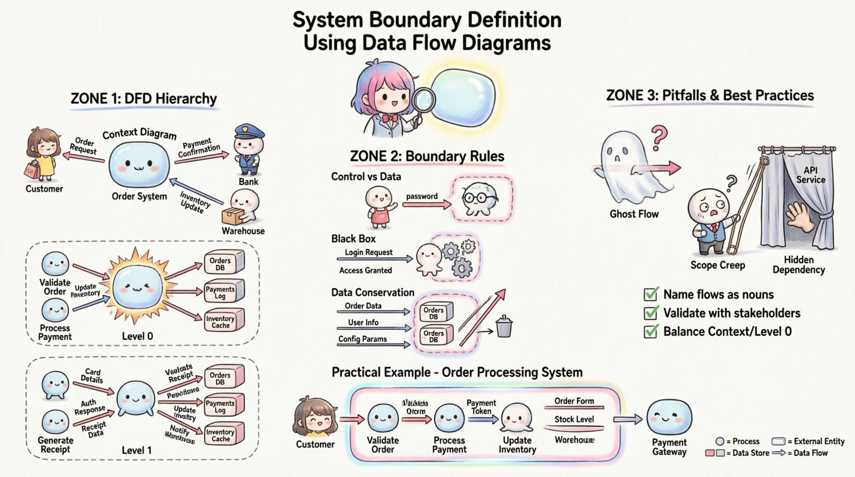
1. Context Diagram (Level 0)
The Context Diagram represents the system as a single bubble. It is the highest level of abstraction. The primary purpose here is to identify the system boundary in its entirety.
- Single Process: The entire system is one circle or rounded rectangle.
- External Entities: All sources and sinks are shown surrounding the process.
- Data Flows: Arrows connect entities to the single process.
- Boundary Definition: The edge of this single bubble is the system boundary.
This diagram answers the question: “What does the system interact with?” It does not show internal details. It only shows the perimeter.
2. Level 0 Diagram (Top Level Decomposition)
Once the boundary is established in the context diagram, it is exploded into major sub-processes. This level maintains the same external boundary but reveals the internal structure.
- Multiple Processes: The single bubble splits into 3 to 7 major processes.
- Internal Data Stores: Repositories appear between processes.
- Boundary Consistency: The external data flows entering and exiting the diagram must match the Context Diagram exactly.
This layer confirms that the boundary definition holds up when the system is broken down. If new external entities appear here that were not in the context diagram, the boundary definition is flawed.
3. Level 1 and Below (Detailed Decomposition)
Sub-processes are further decomposed. The boundary at this level becomes internal. The original system boundary remains the outermost edge of the Level 0 diagram. The internal processes define the logic inside the boundary.
🚧 Defining the Boundary Line
Deciding what falls inside or outside the system boundary requires strict criteria. Ambiguity here leads to technical debt. The following rules help establish a solid line.
Rule 1: Control vs. Data
Systems process data. They do not control the environment. External entities initiate requests. The system responds. The boundary separates control authority from data exchange.
- Inside: Logic, calculation, validation, storage, and transformation of data.
- Outside: Human decision-making, physical world actions, and other independent systems.
For example, if a user enters a password, the user is an external entity. The system checks the password. The boundary is the point where the input data enters the validation process.
Rule 2: The Black Box Principle
To an external entity, the system is a black box. They do not need to know how it works, only what it accepts and returns. The boundary defines the interface contract.
- Inputs must be well-defined and consistent.
- Outputs must be predictable.
- Internal changes should not require changes to external entities.
If changing an internal process forces an external entity to change how it sends data, the boundary definition is too tight or poorly managed.
Rule 3: Data Conservation
Data cannot be created or destroyed at the boundary. It must be transformed. If a flow enters the system, it must exit, or be stored, or be discarded with a clear reason.
- Input Flow: Information enters from an external entity.
- Output Flow: Information leaves to an external entity.
- Stored Flow: Information is saved within a data store inside the boundary.
If data flows appear from nowhere or disappear into nowhere across the boundary, the model is incomplete.
🧩 External Entities vs. Internal Processes
One of the most common errors in boundary definition is confusing an external entity with an internal process. Both interact with data, but their roles differ significantly.
| Feature | External Entity | Internal Process |
|---|---|---|
| Location | Outside the system boundary | Inside the system boundary |
| Function | Source or Destination of data | Transforms data into new form |
| Knowledge | Does not know system internals | Knows system logic and rules |
| Example | Customer, Bank, Supplier | Order Validator, Inventory Checker |
When defining the boundary, ask: “Does this entity transform the data, or does it just send/receive it?” If it transforms, it belongs inside. If it merely provides or consumes, it belongs outside.
⚠️ Common Pitfalls in Boundary Definition
Even experienced analysts can make mistakes when drawing the line. These errors lead to confusion during development and testing.
Pitfall 1: The Ghost Flow
A ghost flow is a data connection that appears to exist but has no logical path. This often happens when a data store is connected to an external entity directly. Data must flow through a process to reach a store. Direct connections between entities and stores bypass the system boundary logic.
Pitfall 2: Scope Creep via the Boundary
Over time, requirements change. Features are added. Sometimes, new functionality is added without updating the boundary. This results in a diagram where the boundary encloses processes that should be external, or vice versa. Regular reviews of the DFD are necessary to keep the boundary aligned with current requirements.
Pitfall 3: Hidden Dependencies
Systems often rely on services not shown on the diagram. For instance, an email server might be treated as a process inside the boundary when it is actually an external service. If the boundary definition hides critical dependencies, integration testing will fail.
Pitfall 4: Confusing Control with Data
Commands are not always data. A “Stop” command is a signal. A “Report” is data. The boundary must distinguish between operational control signals and the data payload being processed.
✅ Best Practices for Clarity
To ensure the boundary definition remains robust, follow these structured practices.
- Use Consistent Notation: Stick to one notation style (e.g., Gane & Sarson or Yourdon & DeMarco) throughout the project. Mixing styles can confuse the boundary line.
- Name Flows Explicitly: Data flows should be named with nouns (e.g., “Invoice,” “Login Request”). Avoid verbs (e.g., “Send Invoice”). The flow represents the data object, not the action.
- Validate with Stakeholders: Walk the diagram with business users. Ask them if the external entities match their view of the system.
- Check Balance: Ensure inputs and outputs match between the Context Diagram and the Level 0 Diagram. The same data flows must appear at the boundary in both views.
- Document Assumptions: If a decision is made to treat a specific third-party service as internal, document why. This helps future maintainers understand the boundary logic.
🔬 Validation and Review Techniques
Once the boundary is defined, it must be tested against reality. Use the following techniques to verify accuracy.
1. The Handoff Test
Imagine handing the system over to a different team. If the boundary is clear, the receiving team knows exactly what inputs to expect and what outputs to deliver. If they are unsure, the boundary is fuzzy.
2. The Security Audit
Security boundaries often align with logical system boundaries. Review the DFD with security protocols. Ensure that sensitive data flows do not cross the boundary without encryption or proper authentication checks. The boundary defines where trust ends.
3. The Performance Stress Test
Consider where bottlenecks occur. If a data flow crossing the boundary is too large, the boundary definition might need adjustment to process data in chunks. This often requires splitting a process or adding a queue.
📝 Practical Example: Order Processing System
Consider a system designed to handle customer orders. The boundary definition determines how the order moves from the customer to the warehouse.
Context Diagram Analysis
External Entities:
- Customer
- Payment Gateway
- Warehouse Management System
System Boundary:
The “Order Processing System” bubble sits between these three entities.
Data Flows Across Boundary:
- Customer → System: Order Details, Payment Info
- System → Customer: Order Confirmation, Shipping Status
- System → Payment Gateway: Transaction Request, Authorization Result
- System → Warehouse: Picking List, Inventory Update
Level 0 Diagram Analysis
Inside the boundary, the single process explodes into:
- Process 1.0: Validate Order
- Process 2.0: Process Payment
- Process 3.0: Update Inventory
- Data Store 1.0: Order Database
- Data Store 2.0: Customer Profile
Boundary Check:
Notice that the Payment Gateway remains outside. The system sends a request, receives a result, but does not process the funds itself. This keeps the financial liability boundary clear. The Warehouse System remains outside because it manages physical stock, not digital order records.
🔗 Integration and Interoperability
In modern architectures, systems rarely exist in isolation. Microservices and APIs complicate the boundary definition. A DFD helps visualize these interactions without getting bogged down in technology specifics.
- API Gateways: If an API Gateway handles routing, it can be part of the boundary or an external entity depending on whether it performs business logic.
- Third-Party Services: If a service provides a core feature (e.g., Map Integration), is it a dependency or a process? If the system cannot function without it, treat it as a critical external entity.
- Legacy Systems: Older systems often act as external entities. They may lack modern interfaces. The DFD boundary must accommodate these data constraints.
📉 Impact on Maintenance and Evolution
A well-defined boundary simplifies future changes. When requirements evolve, you know exactly where to make modifications.
- Adding Features: If you add a new feature, check the boundary. Does it require new external entities? If so, update the Context Diagram.
- Removing Features: If a feature is deprecated, remove the associated flows. Ensure the boundary remains balanced.
- Refactoring: If internal processes are refactored, the boundary should not change. This ensures stability for external partners.
Teams that neglect boundary definition often find themselves rewriting the entire system because the initial scope was unclear. This leads to wasted resources and delayed timelines. A precise DFD acts as a contract between the development team and the business stakeholders.
🛠️ Checklist for Boundary Review
Before finalizing any DFD, run this checklist to ensure the boundary is sound.
- ☐ Does every data flow have a source and a destination?
- ☐ Are all external entities clearly defined with a role?
- ☐ Do all internal processes transform data?
- ☐ Are there any direct connections between entities and data stores?
- ☐ Do the inputs/outputs match between Context and Level 0 diagrams?
- ☐ Is the boundary consistent with the security requirements?
- ☐ Have stakeholders confirmed the scope of the system?
- ☐ Are data names consistent across the diagram?
🔄 Iterative Refinement
System definition is rarely a one-time event. As you gain understanding of the business, the boundary may shift. This is normal. The DFD is a living document. It evolves as the project progresses.
Do not treat the first draft as final. Use early versions to identify gaps. Use later versions to confirm stability. The value lies in the discussion around the diagram, not just the diagram itself. The act of drawing the boundary forces the team to agree on what is inside and what is outside.
By adhering to these principles, you create a clear, maintainable, and robust system architecture. The Data Flow Diagram becomes more than a drawing; it becomes a blueprint for success. It clarifies responsibilities, defines interfaces, and prevents scope creep. It ensures that everyone involved understands the edge of the system.