Now Reading: The Comprehensive Guide to Static Modeling in UML: Concepts and AI Integration
-
01
The Comprehensive Guide to Static Modeling in UML: Concepts and AI Integration


The Comprehensive Guide to Static Modeling in UML: Concepts and AI Integration
Understanding Static Modeling in UML
In the realm of software engineering, static modeling serves as the fundamental bedrock of system design. Unlike dynamic modeling, which simulates behavior over time, static modeling in Unified Modeling Language (UML) focuses strictly on the structural aspects of a system. It identifies what elements exist, how they are organized, and the fixed relationships between them. It functions essentially as a software blueprint, providing a stable view of resources to ensure that developers, architects, and stakeholders share a unified conceptual baseline before coding begins.

Static modeling is concerned with the “nouns” of a system—the classes, objects, components, and nodes—rather than the “verbs” or processes. By defining the main structure that remains stable throughout execution, teams can mitigate architectural risks and ensure scalability.
The Core Pillars of Static Modeling
To capture the static view of a system effectively, UML utilizes several specific diagram types. Each serves a unique purpose in defining the hierarchy and composition of the software architecture.
1. Class Diagrams: The Backbone of UML
Class diagrams are arguably the most critical component of static modeling. They define the system’s schema by outlining:

Static modeling in UML represents the structural aspects of a software system—identifying what elements exist and how they are organized, rather than how they behave over time. It acts like a software blueprint, providing a fixed view of resources and their relationships to ensure a shared conceptual baseline for the team.
Key Concepts of Static Modeling
Static modeling focuses on the main structure of the system, which remains stable throughout execution. The core diagrams include:
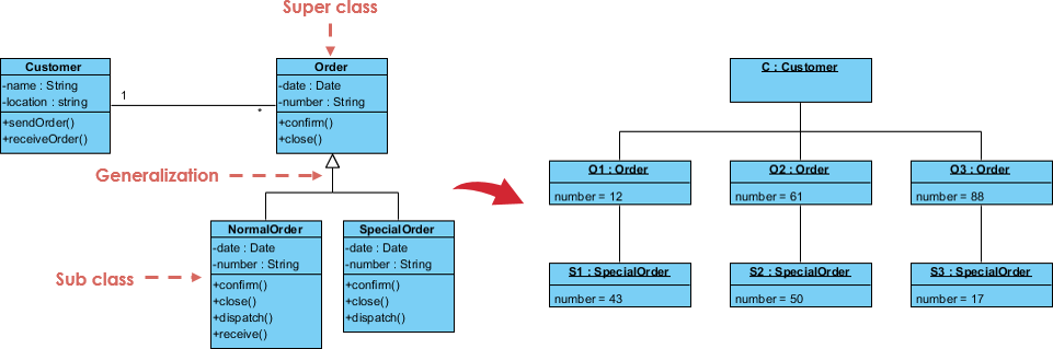
- Class Diagrams: The backbone of UML modeling. They define “nouns” (classes), their attributes (data), and their operations (behavioral signatures). They establish the rules for how objects should relate through associations, aggregations, and compositions.
- Object Diagrams: These model facts or snapshots of a running system at a specific moment. They are primarily used as examples to test the rules established in Class Diagrams.
 Package Diagrams: These are used to group elements into higher-level units, providing a way to organize complex architectures and manage namespaces.
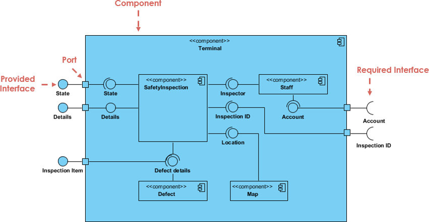
- Component Diagrams: These model the physical implementation view, showing software artifacts like executables, libraries, and files.
- Deployment Diagrams: These map software components onto physical or virtual infrastructure (nodes), such as AWS instances or database servers.
Real-World Examples
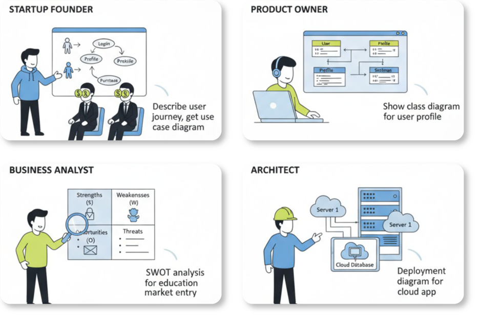
Teams use the Visual Paradigm AI ecosystem to generate static models for various domains:
- Fintech: Modeling a loan application system including classes for
Users,Applicants,LoanTypes, andCreditScores. - Healthcare: Creating a hospital management system with
Patient,Doctor,Appointment, andMedicalRecordclasses. - Cloud Infrastructure: Visualizing an e-commerce inventory system that maps
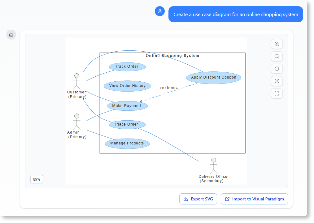
AWS EC2nodes toLambdafunctions andDynamoDBdatabases. - E-commerce: Identifying relationships where “a customer places many orders” and “an order contains many products”.
How Visual Paradigm AI Boosts Static Modeling
Visual Paradigm AI transforms modeling from a “labor-intensive drawing chore” into an intuitive, conversational workflow. It boosts productivity through the following mechanisms:
 Instant Text-to-Diagram Generation: Users can describe a system in plain English, and the AI produces standardized, technically valid models in seconds.
- AI-Powered Textual Analysis: This tool extracts candidate classes, attributes, and relationships from unstructured problem descriptions before a line is drawn, ensuring core logic is captured accurately.
- Diagram “Touch-Up” Technology: Refinement is iterative; users can command the AI to “add a backup server” or “rename this class,” and the system updates the model while maintaining layout integrity.
- Architectural Critique: The AI acts as a consultant, analyzing static models to identify single points of failure or logic gaps, and suggesting industry-standard patterns like MVC.
- Standardized Intelligence: Unlike generic LLMs that may violate modeling rules, VP AI is uniquely trained on official UML 2.5 standards, ensuring that inheritance and multiplicities are semantically correct.
- 10-Step AI-Assisted Wizard: For educational or high-precision needs, a guided wizard leads users through a logical sequence from defining purpose to final analysis reports.
- Classes: The blueprint for objects (the “nouns”).
- Attributes: The data contained within those classes.
- Operations: The behavioral signatures or methods available.
More importantly, class diagrams establish the business rules governing how objects relate to one another through associations, aggregations, and compositions, forming the logical structure of the application.
2. Object Diagrams
While class diagrams provide the abstract rules, object diagrams model specific facts. They represent snapshots of a running system at a particular moment in time. These diagrams are primarily used to test the accuracy of class diagrams by validating specific examples and scenarios.
3. Package Diagrams
As systems grow in complexity, organizing elements becomes crucial. Package diagrams group related elements into higher-level units. This helps in managing namespaces and visualizing the modular structure of complex architectures, ensuring the system remains maintainable.
4. Physical Implementation Views
Static modeling also extends to the physical world through:
- Component Diagrams: These illustrate the organization of software artifacts, such as executables, libraries, and source files, showing how the system is physically constructed.
- Deployment Diagrams: These map the software components onto the hardware or virtual infrastructure. They visualize nodes, such as database servers or AWS instances, ensuring the infrastructure supports the software requirements.

Real-World Applications of Static Modeling
Static modeling is industry-agnostic and vital for clarifying requirements across various domains. Modern teams leverage these models to solve complex domain-specific problems:
- Fintech: Architects model loan application systems by defining classes for
Users,Applicants,LoanTypes, andCreditScoresto ensure data integrity and security. - Healthcare: Hospital management systems are designed with relationships between
Patient,Doctor,Appointment, andMedicalRecordentities to manage sensitive care workflows. - Cloud Infrastructure: DevOps engineers visualize inventory systems by mapping
AWS EC2nodes toLambdafunctions andDynamoDBdatabases, clarifying the deployment topology. - E-commerce: Business analysts identify core relationships, such as “a customer places many orders” and “an order contains many products,” to drive database design.
Revolutionizing Design with Visual Paradigm AI
Traditionally, creating UML diagrams was a labor-intensive chore requiring manual drawing and strict adherence to syntax. Visual Paradigm AI has transformed this process into an intuitive, conversational workflow, significantly boosting productivity and accuracy.
Instant Text-to-Diagram Generation
Visual Paradigm AI allows users to describe a system in plain English. The AI engine processes this natural language input and produces standardized, technically valid models in seconds. This eliminates the blank-page syndrome and accelerates the initial drafting phase.
AI-Powered Textual Analysis
Before a single line is drawn, the AI performs deep textual analysis on unstructured problem descriptions. It automatically extracts candidate classes, attributes, and relationships, ensuring that the core business logic is captured accurately from the requirements documents.
Iterative Refinement and “Touch-Up”
Modeling is rarely perfect on the first try. Visual Paradigm AI supports an iterative workflow where users can command the system to “add a backup server” or “rename this class.” The “Touch-Up” technology updates the model dynamically while maintaining layout integrity, removing the need for manual realignment.
Architectural Critique and Standardization
One of the most powerful features is the AI’s ability to act as a virtual consultant. It analyzes static models to identify single points of failure or gaps in logic, suggesting industry-standard patterns like MVC (Model-View-Controller). Unlike generic Language Models (LLMs) that may hallucinate invalid syntax, Visual Paradigm AI is trained on official UML 2.5 standards. This ensures that inheritance hierarchies and multiplicities are semantically correct, making the models suitable for professional implementation.