


Introduction to UML
The Unified Modeling Language (UML) is the industry-standard visual modeling language used to specify, visualize, construct, and document the artifacts of a software system. Created to bring order and clarity to complex software development, UML provides a rich set of graphical notations that enable software engineers, architects, designers, business analysts, and stakeholders to communicate ideas effectively and unambiguously.
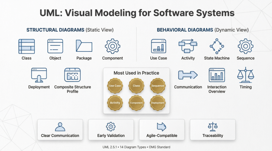
Originally developed in the mid-1990s by Grady Booch, James Rumbaugh, and Ivar Jacobson (the “Three Amigos”), UML unified several popular object-oriented modeling methods of that era. It was later adopted and standardized by the Object Management Group (OMG). The current version, UML 2.5.1, defines 14 types of diagrams that together offer both structural (static) and behavioral (dynamic) perspectives of a software system.
UML is not a programming language, nor is it a software development methodology. Instead, it serves as a universal modeling language that can be used across various processes — from traditional Waterfall and Rational Unified Process (RUP) to modern Agile and DevOps practices.
In today’s software development landscape, UML remains highly relevant for:
- Capturing and validating requirements
- Designing robust system architectures
- Facilitating clear communication among technical and non-technical teams
- Reducing ambiguity and misunderstandings
- Supporting analysis, design, implementation, and maintenance phases
- Enabling traceability from requirements to code
While some criticize UML for encouraging excessive documentation, when used judiciously — especially with lightweight and iterative approaches — it continues to be one of the most powerful tools for thinking through complex problems and producing maintainable, well-designed software systems.
What is UML?
UML (Unified Modeling Language) is the standardized visual modeling language for specifying, visualizing, constructing, and documenting the artifacts of software systems. Developed by the Object Management Group (OMG), UML provides a common notation that helps software engineers, architects, designers, developers, testers, and stakeholders communicate complex ideas unambiguously.

UML is not a programming language, methodology, or process. It is a modeling language that can be used with various processes (Waterfall, Agile, RUP, etc.). It supports both structural (static) and behavioral (dynamic) views of a system.
History and Versions
-
UML 1.0 was proposed in 1997 by combining methods like Booch, OMT, and Use Case modeling.
-
UML 2.0 (2005) introduced major improvements, including better support for components, interactions, and activities.
-
Current version: UML 2.5.1 (minor updates to UML 2.5). It defines 14 diagram types
UML helps in:
-
Requirements analysis
-
System design and architecture
-
Code generation/reverse engineering (with tools)
-
Documentation and maintenance
-
Communication across technical and non-technical teams
Benefits in Software Development
-
Visualization: Turns abstract requirements into concrete diagrams (“a picture is worth a thousand words”).
-
Communication: Common language reduces misunderstandings between developers, architects, business analysts, and clients.
-
Analysis & Validation: Identify gaps, inconsistencies, or risks early.
-
Traceability: Link requirements to design to implementation.
-
Reusability & Maintainability: Better modular design through clear relationships.
-
Agile Compatibility: Use selectively and iteratively (e.g., lightweight sketches in whiteboarding sessions or PlantUML for version-controlled diagrams).
Best Practice Note: In modern Agile/DevOps, avoid “big upfront design.” Create and refine diagrams just enough to solve the current uncertainty or communicate a decision. Keep diagrams simple, focused, and up-to-date only when they add value.
UML Diagram Classification (UML 2.5)
UML diagrams fall into two main categories:

-
Structure Diagrams (Static view – what the system is):
-
Class Diagram
-
Object Diagram
-
Package Diagram
-
Composite Structure Diagram
-
Component Diagram
-
Deployment Diagram
-
Profile Diagram
-
-
Behavior Diagrams (Dynamic view – what the system does):
-
Use Case Diagram
-
Activity Diagram
-
State Machine Diagram
-
Interaction Diagrams (subset):
-
Sequence Diagram
-
Communication Diagram (formerly Collaboration)
-
Interaction Overview Diagram
-
Timing Diagram
-
-
The most commonly used diagrams in practice are Class, Use Case, Sequence, Activity, Component, and Deployment. Many projects succeed with just 3–5 diagram types.
1. Structural Diagrams
Class Diagram
The most fundamental and widely used UML diagram. It shows the static structure of the system: classes, interfaces, attributes, operations (methods), and relationships.
Key Elements:
-
Class: Rectangle with three compartments (name, attributes, operations).
-
Visibility:
+public,-private,#protected,~package. -
Attributes:
visibility name: type = defaultValue. -
Operations:
visibility name(param: type): returnType. -
Relationships:
-
Association (solid line): General relationship (e.g., “owns”).
-
Aggregation (hollow diamond): “Has-a” (weak, parts can exist independently).
-
Composition (filled diamond): Strong “has-a” (parts die with whole).
-
Generalization/Inheritance (solid arrow with hollow triangle): “Is-a”.
-
Dependency (dashed arrow): Temporary usage.
-
Realization (dashed arrow with hollow triangle): Implements interface.
-
Example Use: Domain modeling, database schema design, OOP class planning.
Object Diagram
A snapshot of a class diagram at runtime, showing specific objects (instances) and their links. Useful for illustrating examples or debugging scenarios.
Package Diagram
Organizes elements into hierarchical namespaces (like folders). Shows dependencies between packages. Helpful for large systems to manage complexity and layering.
Component Diagram
Shows software components (modular, replaceable parts) and their interfaces, ports, and dependencies. Good for high-level architectural views (e.g., microservices, layered architecture).
Composite Structure Diagram
Details the internal structure of a classifier (class/component), showing parts, ports, and connectors. Useful for complex objects with internal collaboration.
Deployment Diagram
Models the physical deployment of artifacts (software) onto nodes (hardware/servers, devices, cloud instances). Shows execution environment, communication paths, and artifacts.
Example: Web app deployed on application servers, database on separate node, load balancer, etc.
Profile Diagram
Extends UML with custom stereotypes, tagged values, and constraints for domain-specific modeling (e.g., for real-time systems or enterprise architecture).
2. Behavioral Diagrams
Use Case Diagram
Captures functional requirements from the user’s perspective. Shows actors (users or external systems) and use cases (goals or functionalities), with relationships like <<include>>, <<extend>>, and generalization.
Purpose: Requirements gathering, scope definition, stakeholder communication.
Example: Online Banking – actors: Customer, Teller; use cases: Login, Transfer Funds, View Balance.
Activity Diagram
Models workflows, business processes, or algorithm steps. Similar to flowcharts but supports concurrency (fork/join), decisions, merges, swimlanes (partitions for actors), and object flows.
Key Symbols:
-
Initial node (filled circle)
-
Action (rounded rectangle)
-
Decision node (diamond)
-
Merge node
-
Fork/Join (thick bars for parallelism)
-
Final node (bullseye)
Uses: Business process modeling, detailed algorithm design, concurrent systems.
State Machine Diagram (Statechart)
Shows the states an object goes through, events that trigger transitions, guards (conditions), and actions. Excellent for reactive systems or objects with lifecycle (e.g., Order: Pending → Paid → Shipped → Delivered).
Interaction Diagrams
Sequence Diagram:
-
Most popular interaction diagram.
-
Shows objects (lifelines) and the sequence of messages exchanged over time.
-
Vertical axis = time.
-
Supports activation bars, return messages, fragments (alt, opt, loop, par for parallel, etc.), and interaction occurrences.
Uses: Detailed object interactions, API call flows, critical business logic.
Communication Diagram (Collaboration):
-
Focuses on the links (relationships) between objects rather than strict sequence. Numbered messages show order. More compact for complex collaborations.
Interaction Overview Diagram:
-
Combines activity diagram flow with interaction references (inline sequence/communication diagrams). High-level overview of control flow.
Timing Diagram:
-
Focuses on timing constraints and state changes over time. Useful for real-time or embedded systems with strict performance requirements.
How to Use UML in the Software Development Lifecycle (SDLC)
UML fits into most processes but usage varies:
-
Requirements Phase: Use Case, Activity diagrams for functional flows; Package for high-level organization.
-
Analysis & Design: Class (domain model), Sequence (key scenarios), State Machine (lifecycles), Component (architecture).
-
Implementation: Class/Component for detailed design; Deployment for infrastructure.
-
Testing: Use cases drive test cases; Sequence/Activity for integration tests.
-
Maintenance: Update diagrams for changes; reverse-engineer from code when needed.
In Agile:
-
Use lightweight, just-in-time modeling.
-
Sketch on whiteboards or use tools like PlantUML (text-to-diagram, great for Git).
-
Focus on “modeling to understand” rather than exhaustive documentation.
-
Refine diagrams during sprint planning or refinement sessions.
In Waterfall/RUP: More comprehensive upfront modeling with traceability.
General Best Practices:
-
Keep diagrams at the right level of abstraction (don’t mix high-level architecture with low-level code details in one diagram).
-
Use consistent notation and naming conventions.
-
Maintain only diagrams that provide ongoing value; delete outdated ones.
-
Link diagrams (e.g., a use case realized by a sequence diagram realized by classes).
-
Collaborate: Involve stakeholders when creating requirements diagrams.
-
Version control diagrams (especially text-based like PlantUML).
-
Avoid “analysis paralysis” – model to resolve uncertainty or communicate decisions.
Popular UML Tools (as of 2026)
-
Free/Open Source: Diagrams.net (draw.io) – excellent general diagramming; PlantUML – text-based, ideal for developers (integrates with Markdown, Git, IDEs); StarUML.
-
Collaborative/Cloud: Visual Paradigm Online (comprehensive UML support).
-
Professional/Enterprise: Visual Paradigm Desktop (broad standards support including SysML, ArchiMate);
Many IDEs (IntelliJ, Visual Studio, Eclipse) have UML plugins for reverse engineering.
Recommendation:
-
Developers/Teams: Start with PlantUML or draw.io.
-
Large projects/Enterprises: Visual Paradigm.
Tips for Effective UML Modeling
-
Start simple – master Class, Use Case, Sequence, and Activity first.
-
Use stereotypes (
<<entity>>,<<service>>,<<controller>>) for clarity. -
Add notes and constraints (
{invariant}) where needed. -
Validate with stakeholders and team.
-
Generate code from models or reverse-engineer when possible (reduces manual sync effort).
-
Combine with other notations (C4 model for architecture, BPMN for business processes) when UML alone isn’t sufficient.
-
Practice with real examples: e-commerce system, banking app, or inventory management.
Learning Path
-
Beginner: Focus on Use Case → Activity → Class → Sequence.
-
Intermediate: Component, Deployment, State Machine.
-
Advanced: Composite Structure, Profiles, Interaction Overview, Timing; tool proficiency; integration with code.
-
Resources: OMG UML specification (for reference), Visual Paradigm guides, and tutorials, Martin Fowler’s UML Distilled (pragmatic classic), and hands-on practice with a tool.
UML remains highly relevant in 2026 for complex systems, architectural documentation, and cross-team communication, especially in regulated industries, large enterprises, or when precision matters. In fast-moving startups, use it selectively as a thinking and communication tool rather than exhaustive documentation.
Mastering UML improves your ability to design robust, maintainable software and collaborate effectively. Start by picking one diagram type relevant to your current project and build from there. Practice by modeling a small system end-to-end.
If you need detailed examples for a specific diagram, a sample project (e.g., online bookstore), or help generating PlantUML code, let me know!
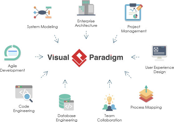
Visual Paradigm: The Recommended UML Tooling for System Developers
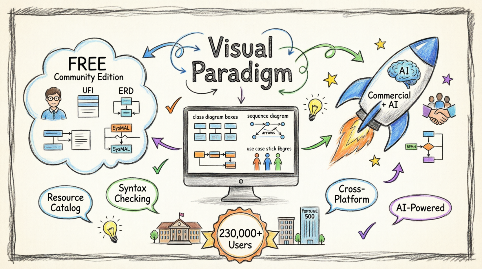
For UML system developers seeking a robust, scalable, and collaborative modeling environment, Visual Paradigm stands out as a premier choice. Whether you’re architecting enterprise-scale systems or iterating rapidly in an agile sprint, Visual Paradigm delivers the precision, flexibility, and integration capabilities modern development teams demand—now supercharged with AI-powered intelligence.
Why UML System Developers Choose Visual Paradigm
✅ AI-Powered Modeling: From Idea to Diagram in Seconds
-
Natural Language to UML: Describe your system in plain text and watch Visual Paradigm’s AI instantly generate accurate, standards-compliant class diagrams, use case diagrams, sequence diagrams, and more .
-
AI-Assisted Class Diagram Generator: Follow a guided 10-step wizard where AI suggests scopes, validates relationships, and produces architectural analysis reports to elevate design quality .
-
Context-Aware Intelligence: The AI interprets your intent, fills in missing details, and suggests relationships to expand ideas into structured, editable models—not static images .
-
Use Case Modeling Studio: Turn high-level goals into complete use case specifications, activity diagrams, and test cases automatically, accelerating requirements-to-design workflows.
✅ Standards-Compliant & Future-Ready Modeling
-
Full support for UML 2.x standards ensures your diagrams are interoperable, maintainable, and aligned with industry best practices.
-
Extend beyond UML with complementary notations like ERD, BPMN, DFD, and Mind Maps—all within a single, unified workspace.
-
Generate REST API class diagrams via SWAGGER and model data layers using ORM/Hibernate, bridging design and implementation seamlessly.
✅ Code-Centric Engineering & Round-Trip Sync
-
Perform forward and reverse engineering for Java, C++, and other popular languages—keeping your models and codebase in sync.
-
Visualize database schemas alongside class structures, enabling end-to-end system modeling from concept to persistence layer.
-
Reduce technical debt by detecting design-code mismatches early through automated consistency checks.
✅ Collaborative Modeling for Distributed Teams
-
Manage model versioning, track changes, and resolve conflicts with built-in team collaboration features.
-
Interlink UML artifacts with user stories, sprint backlogs, wireframes, and glossaries—creating traceability from requirement to implementation.
-
Host models securely on-premises or in the cloud, with desktop editions bundled free with Visual Paradigm Online for maintenance subscribers.
✅ Agile & Enterprise Flexibility
-
Adapt your workflow: use Visual Paradigm for ad-hoc sketching or embed it deeply into Scrum, SAFe, or TOGAF processes.
-
Leverage STEP-guided workflows (e.g., Use Case 2.0) to standardize analysis while preserving team autonomy.
-
Generate professional HTML/PDF reports automatically—ideal for stakeholder reviews, audits, or handoffs.
✅ Intelligent Analysis & Evolution Support
-
Use Visual Diff to compare model versions and understand architectural changes at a glance.
-
Perform impact analysis before modifying models, reducing regression risk in complex systems.
-
Extract scattered diagram metadata into structured tables using ETL technology, enabling data-driven design decisions.
Built for Real-World Development Workflows
Visual Paradigm isn’t just a diagramming tool—it’s a lifecycle integration platform. By connecting UML models to backlog management, task tracking, documentation, and code generation, it eliminates silos and ensures that architectural intent flows cleanly into delivery. Its cross-platform support (Windows, macOS, Linux) and active community further lower adoption barriers for diverse teams.
💡 Pro Tip for Developers: Start with the AI-Assisted Class Diagram Generator to rapidly prototype your domain model, then expand to link diagrams with sprint backlogs or generate Swagger specs. The AI handles layout and validation so you can focus on architecture.
Trusted at Scale
From startups to Fortune 500 enterprises, government agencies, and academic institutions, Visual Paradigm powers modeling workflows where correctness, collaboration, and clarity matter. For UML system developers who value precision without sacrificing agility—and now want AI to accelerate the tedious parts of modeling—it offers an unmatched balance of power, intelligence, and usability.
Recommendation: If your team relies on UML to communicate architecture, drive implementation, or document system behavior, Visual Paradigm provides the most comprehensive, integrated, and developer-friendly environment available today. With its AI-powered ecosystem, you can go from concept to validated design in minutes, not days. Begin with a free trial to experience how seamless, intelligent model-driven development can be
Summary of UML for Software Development
The Unified Modeling Language (UML) provides a standardized way to model software systems through 14 diagram types, divided into two major categories. Among these, the most frequently used diagrams in real-world software development are:
- Use Case Diagram – for requirements and scope
- Class Diagram – for static structure and domain modeling
- Sequence Diagram – for object interactions and flows
- Activity Diagram – for workflows and business processes
- Component & Deployment Diagrams – for architectural and physical views
UML supports the entire software development lifecycle, from requirements gathering and analysis through design, implementation, testing, and maintenance. In Agile environments, it is best applied using a “just enough” modeling approach — creating diagrams iteratively to solve specific problems, clarify design decisions, or improve communication, rather than producing exhaustive upfront documentation.
Key Benefits of using UML include improved communication, early detection of design flaws, better system understanding, and enhanced maintainability. However, its effectiveness depends heavily on using the right diagram at the right level of abstraction and keeping models practical and up-to-date.
Modern tools such as PlantUML, draw.io (diagrams.net), and Visual Paradigm make creating and maintaining UML diagrams easier than ever, with many supporting text-based diagramming that integrates well with version control systems.
While software development practices have evolved significantly, UML remains a foundational skill for professional software engineers and architects. Mastering UML empowers you to design clearer, more robust, and better-documented systems, and significantly improves collaboration across diverse project teams.
Whether you are building a small application or a large-scale enterprise system, a solid understanding of UML will help you think more systematically and communicate your designs more effectively.