


Understanding User Scenarios in UML
In the Unified Modeling Language (UML), user scenarios serve as the fundamental backbone for understanding system behavior. A scenario is formally defined as a single logical path through a Use Case, representing a specific instance of execution or a distinct outcome. Unlike high-level requirements which may be abstract, scenarios provide the concrete steps necessary to validate logic.
To effectively model these scenarios, systems analysts and architects rely on a combination of diagrams and narratives. The primary methods include:
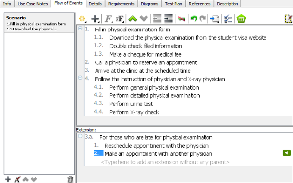
- Use Case Narratives: These are textual descriptions that provide a step-by-step dialog of the interaction between an actor and the system, often detailing the “happy path” as well as alternative flows.
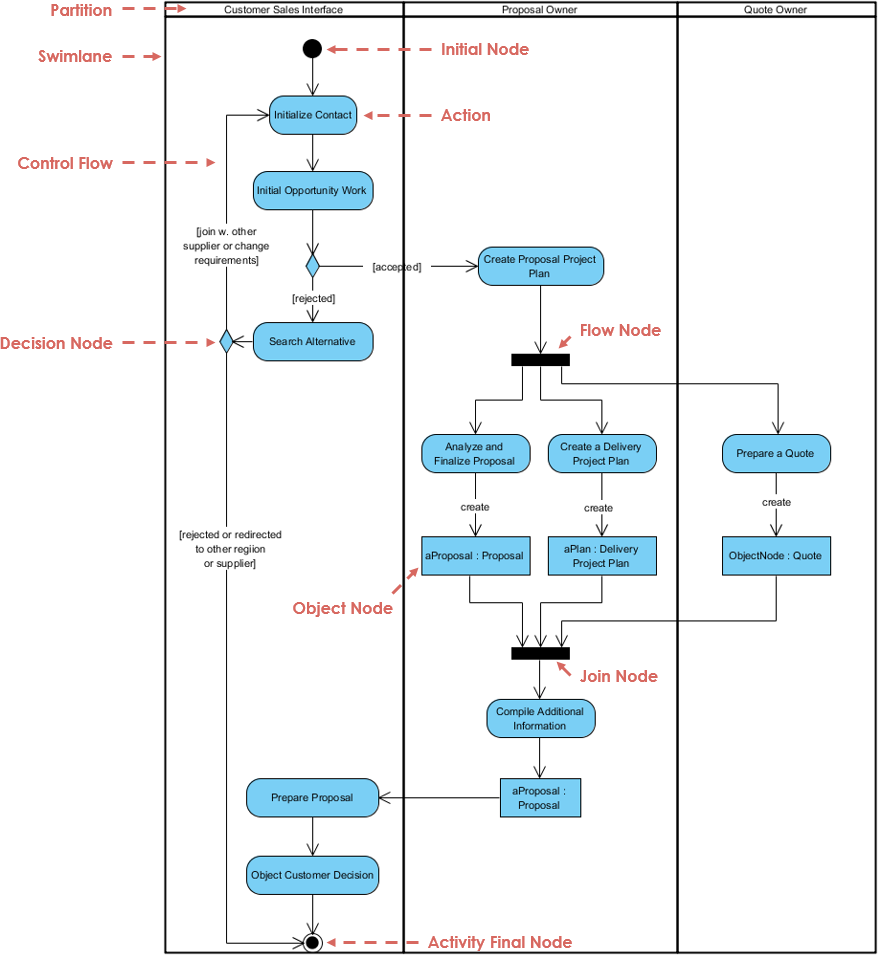
- Activity Diagrams: These diagrams visually map the logic of Use Case scenarios. They are crucial for revealing decision points, loops, and parallel flows that text might obscure.
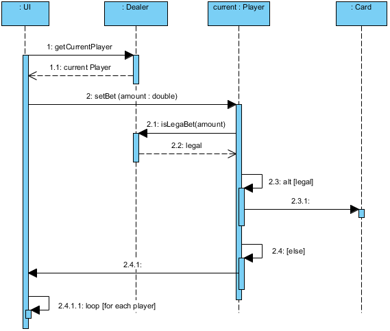
- Sequence Diagrams: Focused on time-ordered interactions, Sequence Diagrams capture the behavior of a single scenario by illustrating the message exchanges between specific objects.
- Collaboration (Communication) Diagrams: Providing an alternative view to sequence diagrams, these emphasize the structural organization of the objects participating in a specific scenario.

The Strategic Importance of Visual Diagrams
Visual diagrams are not merely documentation; they act as a shared conceptual baseline between technical developers and business stakeholders. Without them, complex projects risk becoming a “maze without a map.” By translating high-level and often vague requirements into precise blueprints, teams can secure project success.
The utility of these diagrams extends across the development lifecycle:
- Identifying Logical Gaps: Visualizing flows helps teams spot missing error-handling states and logic holes early in the design phase.
- Bridging Communication: Diagrams serve as a universal language, facilitating clearer understanding between non-technical stakeholders and engineering teams.
- Ensuring Architectural Integrity: They allow architects to visualize dependencies, helping to identify potential single points of failure.
- Documentation and Validation: Complex system behaviors are documented and validated more clearly through visual means than through text alone.
Transforming Modeling with Visual Paradigm AI
Traditional modeling can be a time-consuming process. The Visual Paradigm AI Platform transforms this from a “labor-intensive drawing chore” into an automated, conversational workflow. This shift allows architects to focus on design logic rather than the mechanics of drawing tools.
Key AI Capabilities
The platform introduces several features that streamline the creation and refinement of UML diagrams:
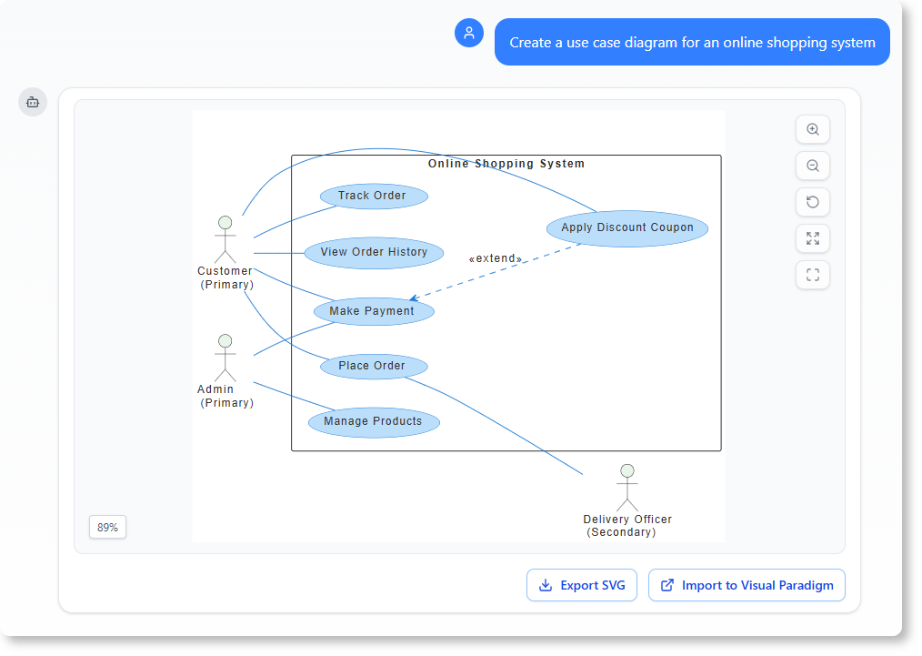
- Instant Text-to-Diagram Generation: Users can create accurate, UML-compliant diagrams instantly from simple natural language descriptions.
- Iterative Diagram Touch-Up: Unlike general Large Language Models (LLMs) that often require a full redraw to make changes, Visual Paradigm allows for iterative refinement. Users can issue commands like “add a backup server,” and the AI modifies the diagram while maintaining layout integrity.
- Architectural Critique: Acting as a digital design consultant, the AI identifies logic gaps or single points of failure and suggests industry-standard patterns, such as MVC (Model-View-Controller).
- Textual Analysis: The system parses unstructured problem descriptions to extract candidate classes and relationships before a single line is manually drawn.
The Visual Paradigm AI Ecosystem
The Visual Paradigm ecosystem is designed as a multi-faceted environment for professional engineering, integrating various tools to support the full software development lifecycle (SDLC).
Components of the Ecosystem
| Component | Function |
|---|---|
| AI Chatbot | Acts as a “conversational bridge” for rapid prototyping and performs non-destructive “Touch-Up” edits to existing diagrams. |
| AI Step-Based Apps | Includes guided tools like the 10-Step Wizard and Textual Analysis Tool, providing educational tips and systematic requirement extraction. |
| Embedded Diagram Generator | An “integrated engine” within the Desktop environment designed for high-precision tasks, such as generating complex UML Package and Timing diagrams. |
| AI Image Translator | Localizes technical diagrams into over 50 languages, ensuring that connectors and structural integrity are perfectly preserved during translation. |
| Integration Suite | Ensures that AI-generated models are functional artifacts rather than static images. These models can be imported for code engineering, database generation, and ORM integration. |
By leveraging these tools, teams can move from abstract user scenarios to concrete, executable code and database structures with greater speed and accuracy.