


UML class diagrams evolve throughout the software development lifecycle, reflecting increasing levels of detail and technical specificity. Below is a breakdown of how they differ across key development stages, along with examples and best practices.
1. Requirements/Analysis Stage – Conceptual (Domain) Model
Purpose: Capture business concepts and relationships without technical implementation details.
Characteristics:
- Focus on domain entities and their relationships
- No methods or implementation details
- Minimal or no visibility modifiers
- Abstract and technology-agnostic
Example:

@startuml

skinparam {
' Overall style
roundcorner 8

' Colors
ArrowColor #444444
ArrowFontColor #444444
BorderColor #444444

' Class styling
Class {
BorderColor #1A237E
BackgroundColor #E8EAF6
FontColor #1A237E
}

' Package styling
Package {
BorderColor #6D876D
BackgroundColor #E6F0E6
FontColor #3D553D
}
}

package "E-commerce System" {
class "Customer" {
-name : String
-email : String
-address : String
}

class "Order" {
-orderId : String
-date : Date
-total : Double
}

class "OrderItem" {
-productId : String
-productName : String
-quantity : Int
-unitPrice : Double
}
}

Customer --|> Order : "places" "1"
Order o-- "many" OrderItem : "contains"
Order --> "0..*" OrderItem : "has items"

' Optional dependency
OrderItem --> Customer : "referenced by"

hide class circle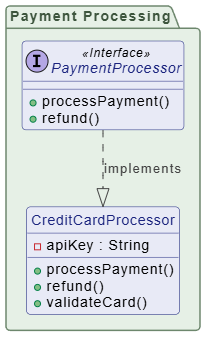
@enduml2. Design Stage – Design Model
Purpose: Define system structure, responsibilities, and interactions in preparation for implementation.
Characteristics:
- Includes classes, interfaces, and relationships
- Shows method signatures and visibility
- May include design patterns
- Still platform-independent
Example:
@startuml

skinparam {
' Overall style
roundcorner 8

' Colors
ArrowColor #444444
ArrowFontColor #444444
BorderColor #444444
' Class styling
Class {
BorderColor #1A237E
BackgroundColor #E8EAF6
FontColor #1A237E
}

' Interface styling
Interface {
BorderColor #A7C5C5
BackgroundColor #E0F2F1
FontColor #444444
}

' Package styling
Package {
BorderColor #6D876D
BackgroundColor #E6F0E6
FontColor #3D553D
}
}

package "Payment Processing" {
interface "PaymentProcessor" <<Interface>> {
+processPayment()
+refund()
}

class "CreditCardProcessor" {
-apiKey : String
+processPayment()
+refund()
+validateCard()
}
}

PaymentProcessor ..|> CreditCardProcessor : implements

' Ensure no class is isolated — all classes are connected
hide class circle

@enduml3. Implementation Stage – Implementation Model
Purpose: Reflect actual code structure, including language-specific details. Characteristics:
- Matches actual source code
- Includes all attributes, methods, visibility, and types
- Shows inheritance, interfaces, and dependencies
- May include framework-specific constructs
Example (Java-style):

4. Maintenance Stage – As-Built Documentation
Purpose: Document the actual deployed system for future reference and maintenance.
Characteristics:
- Reverse-engineered from code
- Includes all implementation details
- May be auto-generated
- Used for onboarding, debugging, and refactoring
Example:
┌────────────────────────────────────┐
│   @Entity                          │
│   public class Customer            │
├────────────────────────────────────┤
│ - @Id customerId: Long             │
│ - @Column name: String             │
│ - @OneToMany orders: List<Order>   │
│ - @Version version: Integer        │
├────────────────────────────────────┤
│ + @PrePersist validate()           │
│ + @PostLoad initialize()           │
└────────────────────────────────────┘
Comparison Table
| Aspect | Analysis | Design | Implementation | Maintenance |
|---|---|---|---|---|
| Detail Level | Low | Medium | High | Very High |
| Methods | None | Signatures only | Full implementation | Full + annotations |
| Visibility | Not shown | Shown | Shown | Shown |
| Technology | Independent | Independent | Specific | Specific |
| Audience | Stakeholders | Architects | Developers | Maintainers |
| Update Frequency | Early phase | Design phase | During coding | Post-deployment |
Best Practices by Stage
✅ Analysis Stage
- Keep it simple and focused on business concepts
- Avoid technical jargon
- Validate with domain experts
✅ Design Stage
- Apply design patterns where appropriate
- Ensure scalability and modularity
- Review with technical team
✅ Implementation Stage
- Keep diagrams synchronized with code
- Use tooling for auto-generation where possible
- Document non-obvious design decisions
✅ Maintenance Stage
- Auto-generate from code when feasible
- Highlight changes in versioned diagrams
- Use for impact analysis and onboarding
🛠️ Tooling: Visual Paradigm – A Unified Platform for Evolving Class Diagrams
While PlantUML offers a lightweight, code-based approach to UML modeling, Visual Paradigm stands out as a comprehensive, enterprise-grade tool that perfectly supports the full lifecycle of class diagrams — from conceptual modeling to detailed design and ongoing maintenance.
Designed for teams of all sizes, Visual Paradigm provides a rich, visual environment that enables developers, architects, and analysts to create, refine, and collaborate on class diagrams with precision and agility — all while aligning with real-world development workflows.
✅ Why Visual Paradigm Fits This Evolutionary Approach
| Development Stage | Visual Paradigm Features | Benefit |
|---|---|---|
| Conceptual Design | Drag-and-drop domain modeling, intuitive class creation, natural language input for quick prototyping. | Rapidly sketch high-level entities and relationships without technical clutter. |
| Analysis & High-Level Design | Built-in support for stereotypes (<<entity>>, <<interface>>), association roles, and multiplicity editing. |
Easily distinguish between abstract concepts and concrete structures. |
| Detailed Design | Full attribute/method specification with data types, visibility, and constraints. Real-time validation and code generation (Java, C#, Python, etc.). | Prepare diagrams for implementation with minimal friction. |
| Maintenance & Evolution | Version control integration, change tracking, and diagram comparison tools. Supports renaming, refactoring, and dependency analysis. | Track how processors, services, and classes evolve over time — ideal for documenting refactoring and deprecations. |
🔧 Advanced Capabilities for Connected Design
Visual Paradigm goes beyond basic diagramming by enabling design patterns like Strategy and Factory through:
- Pattern templates (e.g., Strategy, Factory, Singleton) with pre-built structure.
- Dependency injection support via UML stereotypes and component diagrams.
- Reverse engineering from code and forward engineering to code — keeping diagrams in sync with reality.
- Integrated collaboration via cloud workspace, comments, and team reviews.
For example, when modeling the payment processor subsystem, you can:
- Use the Strategy Pattern template to auto-generate
PaymentProcessorand its implementations. - Apply the Factory Pattern with a visual factory class and connection arrows.
- Generate code stubs instantly — ensuring the diagram and code evolve together.
📌 Real-World Workflow Example
- Design Phase: A team sketches a conceptual class diagram in Visual Paradigm using simple shapes and relationships.
- Refinement: As the system evolves, they add attributes, methods, and stereotypes — turning it into a detailed design.
- Code Generation: The class diagram is used to generate Java classes with proper
@Overrideand@Injectannotations. - Maintenance: When adding
StripeProcessor, the team uses the diagram comparison tool to spot differences and update documentation automatically.
💡 Final Verdict
While PlantUML excels in automation, version control, and lightweight documentation, Visual Paradigm is the ideal choice for teams seeking end-to-end UML modeling, collaborative design, and tight integration with development practices. It transforms class diagrams from static artifacts into living, evolving documents that drive architecture, guide implementation, and support long-term system health.
✅ Recommended for: Teams building complex systems where design clarity, collaboration, and traceability are critical — especially in enterprise, agile, or regulated environments.
Let me know if you’d like a comparison table between PlantUML and Visual Paradigm, or a step-by-step tutorial on creating the payment processor diagram in Visual Paradigm! 🚀
By tailoring UML class diagrams to each development stage, teams can ensure clear communication, maintain alignment between design and implementation, and support long-term system maintainability.
UML Diagram Resource
- What Is a Class Diagram? – A Beginner’s Guide to UML Modeling: An informative overview explaining the purpose, components, and importance of class diagrams in software development and system design.
- Complete UML Class Diagram Tutorial for Beginners and Experts: A step-by-step tutorial that walks users through creating and understanding UML class diagrams, ideal for learning software modeling.
- AI-Powered UML Class Diagram Generator by Visual Paradigm: An advanced AI-assisted tool that automatically generates UML class diagrams from natural language descriptions, significantly streamlining the software design process.
- Mastering Swimlane Activity Diagrams: A Practical Guide with Examples: A detailed guide on creating swimlane activity diagrams to visualize workflows across different roles or departments using real-world examples.
- A Guide to Creating Swimlane Activity Diagrams: This resource offers a step-by-step guide on designing swimlane activity diagrams to effectively model business processes with role-based flow.
- How to Draw Class Diagrams in Visual Paradigm – User Guide: A detailed user guide explaining the step-by-step process of creating class diagrams using the Visual Paradigm software platform.
- Real-Life Case Study: Generating UML Class Diagrams with Visual Paradigm AI: A case study showcasing how an AI assistant successfully transformed textual requirements into accurate UML class diagrams for a real-world project.
- Swimlane Diagram Tool for Process Visualization: An overview of a powerful online tool designed for creating swimlane diagrams to map workflows and assign responsibilities across teams.
- Learning Class Diagrams with Visual Paradigm – ArchiMetric: This article highlights class diagrams as a vital tool for modeling the structure of a system in object-oriented design.
-
Introduction to BPMN: Swimlanes: This tutorial explains how swimlanes (pools and lanes) represent the participants in a business process and contain the flow objects performed by those participants.