


Creating robust system models requires a disciplined approach to how information is captured, moved, and retained. In the context of Data Flow Diagrams (DFD), the data store represents the backbone of system persistence. Without a clear design for where data lives, the flow of information remains abstract and unimplementable. This guide explores the core principles of designing data stores within DFDs, ensuring clarity, accuracy, and alignment with system architecture.
Effective modeling goes beyond drawing lines between shapes. It demands a deep understanding of data integrity, access patterns, and the lifecycle of information within the system. By adhering to established design principles, analysts can produce diagrams that serve as reliable blueprints for development teams.
🏷️ Defining the Data Store 🏷️
A data store is a passive element in a Data Flow Diagram. Unlike processes, which transform data, data stores hold data at rest. They represent files, databases, paper records, or any repository where information is saved for later retrieval.
- Passive Nature: Data does not flow out of a store unless a process explicitly requests it.
- Storage Identity: It is not a process itself; it does not change the data, it holds it.
- Visual Representation: Typically depicted as an open-ended rectangle or double vertical lines, depending on the notation standard used.
When designing these elements, the focus must remain on the logical requirement rather than the physical implementation. The DFD describes what data is needed, not how it is physically indexed or stored on a hard drive.
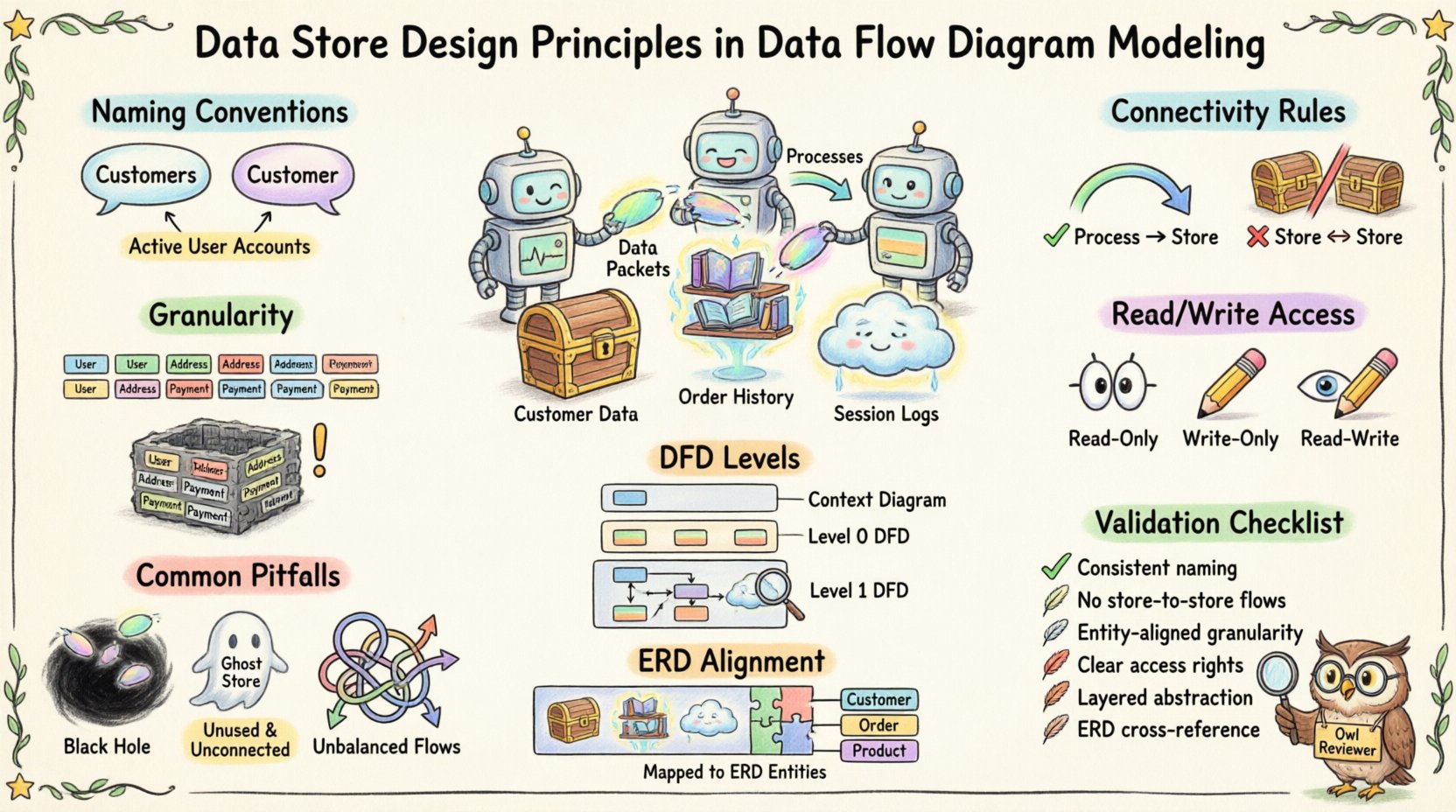
📝 Naming Conventions for Clarity 📝
Naming is the first line of defense against confusion. Ambiguous labels lead to misinterpretation during the design phase. A well-named data store provides immediate context about the information it contains.
1. Singular vs. Plural
Consistency is key. Some teams prefer singular nouns (e.g., Customer) while others use plural (e.g., Customers). The critical factor is that the entire model uses the same convention.
- Recommendation: Use plural nouns for sets of data (e.g., Orders, Products) to imply a collection.
- Exception: Singular names work for specific instances if the store holds only one record type (e.g., Configuration).
2. Descriptive Precision
Avoid generic terms like Data or Info. These labels provide zero insight into the content.
- Bad Example: System Data
- Good Example: Active User Accounts
Specific naming helps stakeholders identify the scope of the store immediately. It reduces the cognitive load required to understand the diagram.
3. Tense and State
Names should reflect the state of the data. If the store holds historical records, the name should reflect that.
- Transaction Logs implies a record of past events.
- Pending Orders implies data awaiting action.
🔗 Connectivity Rules 🔗
The movement of data into and out of a store is governed by strict logical rules. Violating these rules breaks the integrity of the DFD.
1. Process Connection Requirement
A data store must always be connected to at least one process. It cannot exist in isolation.
- Input: A process must write data to the store (e.g., saving a new record).
- Output: A process must read data from the store (e.g., retrieving a record).
If a store is connected to nothing, it is a ghost element with no function. If it is connected to multiple processes, the flow of data must be clearly defined for each connection.
2. No Direct Store-to-Store Flow
Data cannot move directly from one data store to another without a process in between. This rule enforces the principle that data transformation or validation occurs before storage.
- Incorrect: Line connecting Store A directly to Store B.
- Correct: Process X reads from Store A, transforms the data, and writes to Store B.
This separation ensures that business logic, validation, or formatting is applied before data persists. It prevents the model from suggesting that data is simply copied without oversight.
3. Data Flow Labeling
Every line connecting a process to a data store must be labeled. The label describes the specific data moving across that boundary.
- Example: A line from Order Process to Order Store might be labeled Order Details.
- Example: A line from Order Store to Report Process might be labeled Order History.
Labels provide context for the volume and type of data being transferred. They help developers understand the schema requirements later.
🎯 Granularity and Scope 🎯
Deciding how to split data into stores is a critical design decision. Too many stores fragment the model, while too few create a monolithic block of information.
1. Entity-Based Grouping
Group data by logical entity. If the system tracks customers, products, and invoices, these should generally reside in separate stores.
- Benefit: Simplifies maintenance. Changes to customer data do not impact invoice storage logic.
- Benefit: Reduces the risk of accidental data corruption during updates.
2. Read-Write Separation
Consider whether a store is primarily for reading or writing. High-volume transaction logs often require different storage handling than reference data.
- Reference Data: Stores like Country Codes are read-heavy and rarely change.
- Transaction Data: Stores like Sales Logs are write-heavy and grow over time.
Distinguishing these types helps in planning for capacity and access patterns, even though the DFD remains a logical model.
3. Temporary vs. Permanent
Not all data stores represent permanent retention. Some are temporary buffers.
- Session Data: Stores used for temporary user sessions during a login process.
- Cache Stores: Temporary holding areas for frequently accessed data.
Clearly marking temporary stores prevents confusion regarding data retention policies. A temporary store should be emptied or cleared once the process completes.
🔄 Data Flow and Process Interaction 🔄
The relationship between a process and a data store is bidirectional in many cases, but not always. Understanding the directionality is essential for accurate modeling.
1. Read-Only Access
Some stores are accessed only for reading. A process might query a store to display information without modifying it.
- Example: A Display Profile process reading from User Profile Store.
- Constraint: No data flow arrow should point from the store to the process AND back for the same transaction unless it implies a write operation.
2. Write-Only Access
Some processes write data without needing to retrieve it first.
- Example: An Event Log process writing to System Audit Store.
- Constraint: Ensure the process has the necessary context to write the data correctly without external input.
3. Read-Write Access
Most business processes involve retrieving, modifying, and saving data.
- Example: Update Inventory reads current stock, calculates new amount, and saves it.
- Modeling: Use separate flows for reading and writing to clarify the sequence of operations.
This distinction helps developers understand if a database transaction requires a lock or a commit immediately.
📊 DFD Levels and Store Visibility 📊
DFDs are often decomposed into levels, from Context Diagrams (Level 0) to detailed breakdowns (Level 2, Level 3). Data stores appear differently at each level.
1. Context Level (Level 0)
At the highest level, data stores are often omitted to maintain simplicity. The focus is on external entities and the main system boundary.
- Reason: Too much detail obscures the high-level data exchange.
- Exception: Major external databases might be shown if they are critical to the system boundary.
2. Level 1 Decomposition
As the system is broken down into major processes, data stores become visible. This is where the primary storage architecture is defined.
- Focus: Identify the core repositories required for each major function.
- Detail: Ensure every process has a destination for its output data.
3. Level 2 and Beyond
Further decomposition may split large data stores into smaller, more specific ones.
- Example: Customer Store at Level 1 might split into Contact Info Store and Billing Store at Level 2.
- Consistency: Ensure that data at lower levels matches the data at higher levels. Do not introduce new data types that were not present in the parent diagram.
⚠️ Common Pitfalls ⚠️
Even experienced analysts make mistakes when designing data stores. Avoiding these common errors ensures the diagram remains accurate.
- Black Holes: A process that takes data in but does not write it anywhere. This implies data loss.
- Firestorms: A process that takes data in but creates data out without a store. This implies data is created from nothing (miracle).
- Ghost Stores: Data stores with no connecting processes. These are dead ends.
- Unbalanced Flows: When moving from Level 1 to Level 2, the inputs and outputs must match. If a store is added in Level 2, it must be justified by the inputs/outputs of the parent process.
- Over-Engineering: Trying to model every database table as a separate store in a Level 1 diagram. Stick to logical entities, not physical tables.
📚 Aligning with Data Models 📚
While DFDs focus on flow, they must align with Entity Relationship Diagrams (ERD) or logical data models. The data stores in the DFD should correspond to the entities in the ERD.
- Consistency Check: If the DFD has a Product Store, the ERD should have a Product entity.
- Attribute Mapping: The attributes required by the process to interact with the store must exist in the data model.
- Normalization: While DFDs do not enforce normalization, the design should avoid obvious redundancy that suggests poor database design.
This alignment ensures that the logical design (DFD) can be translated into physical implementation (Database Schema) without significant rework.
🔍 Design Validation Checklist 🔍
Before finalizing a Data Flow Diagram, use the following checklist to validate data store design.
| Principle | Checklist Item | Status |
|---|---|---|
| Naming | Are all store names descriptive and consistent? | ☐ |
| Connectivity | Is every store connected to at least one process? | ☐ |
| Flow Direction | Are arrows pointing correctly between processes and stores? | ☐ |
| Labeling | Is data flowing across lines labeled with content names? | ☐ |
| No Direct Store Links | Are there any lines connecting Store to Store directly? | ☐ |
| Consistency | Do lower-level stores match the parent level scope? | ☐ |
| Integrity | Are all data requirements for processes met by available stores? | ☐ |
🔄 Maintenance and Evolution 🔄
System requirements change. Data stores must be adaptable to these changes without breaking the model.
- Version Control: Keep track of changes to store definitions. If a store splits, document the migration path.
- Legacy Data: Plan for how old data is handled when a store schema changes. This often requires an archive store.
- Feedback Loop: Use feedback from development teams to refine store granularity. If developers find a store too broad, split it. If they find it too fragmented, merge it.
A static model is a liability. The data store design should be reviewed whenever business rules change or new compliance requirements are introduced. This ensures the DFD remains a living document that accurately reflects the system’s data needs.
📝 Conclusion on Implementation
Designing data stores in Data Flow Diagrams is a foundational task for system analysis. It bridges the gap between abstract processes and concrete data persistence. By following strict naming conventions, connectivity rules, and granularity principles, analysts create models that are both readable and actionable.
The goal is not to replicate the database schema perfectly, but to capture the logical necessity of data storage. When the DFD is accurate, the transition to development is smoother, and the risk of data loss or misalignment is significantly reduced. Focus on clarity, consistency, and the logical flow of information to produce high-quality system designs.