


Introduction
As someone who has spent years navigating the complexities of software architecture, I’ve always viewed UML (Unified Modeling Language) as both a powerful ally and an occasional source of frustration. The promise of a universal visual language for system design is compelling, but the reality of manually crafting detailed diagrams can be time-consuming and technically demanding. Recently, I decided to revisit UML with a fresh perspective—exploring how modern AI-powered tools are transforming the modeling experience. What I discovered wasn’t just an incremental improvement, but a fundamental shift in how teams can approach system visualization, requirements gathering, and architectural documentation. This guide shares my practical journey through UML’s core concepts, diagram types, and the exciting new capabilities that are making professional-grade modeling accessible to developers, analysts, and business stakeholders alike.

Understanding UML: A Practitioner’s Perspective
UML remains the industry-standard language for specifying, visualizing, constructing, and documenting software system artifacts. Created by the Object Management Group (OMG), with its 1.0 specification proposed in January 1997, UML has evolved into a versatile general-purpose modeling language. What I appreciate most about UML is its flexibility: while primarily used for software systems, it’s equally effective for modeling non-software processes like manufacturing workflows or business operations.
Key insights from my experience:
-
UML is a general-purpose modeling language that has matured into an OMG standard, supporting both complex software and non-software systems
-
It provides rich elements and components following object-oriented concepts, making it ideal for pictorial representation of OO systems
-
UML diagrams can be drawn from multiple perspectives—design, implementation, deployment—capturing architectural, behavioral, and structural aspects
-
While UML itself isn’t a programming language, modern tools can generate code in various languages directly from UML diagrams
The Purpose of UML: Why It Still Matters
“A picture is worth a thousand words” perfectly encapsulates UML’s value proposition. Before UML’s introduction, object-oriented development lacked standardized methodologies for organizing and consolidating design efforts. UML filled this gap with several important goals:
-
Defining a simple, general-purpose modeling language that’s accessible to all modelers
-
Creating tools usable not just by developers, but also by business users, analysts, and stakeholders
-
Supporting both software and non-software system modeling
-
Clarifying that UML is a modeling mechanism, not a development method—it complements processes rather than replacing them
In my view, UML’s enduring relevance lies in its ability to provide a common visual vocabulary that bridges technical and non-technical team members, reducing miscommunication and accelerating consensus on system design.
Modeling Architecture Views: The 4+1 Framework in Practice
One of UML’s most powerful aspects is its support for the 4+1 Views of Software Architecture. This framework acknowledges that different stakeholders need different perspectives on the same system. Here’s how I’ve found these views valuable in real projects:
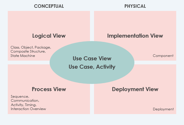
Use Case View (The Central Connector)
-
Describes system functionality, external interfaces, and principal users
-
Contains the Use-Case Model, which I’ve found essential for deriving all architectural elements from requirements
-
Mandatory in the 4+1 framework and invaluable for stakeholder alignment
Logical View
-
Shows system structure in terms of implementation units: packages, classes, interfaces
-
Illustrates dependencies, interface realizations, and part-whole relationships
-
Critical for developers understanding the codebase structure
Implementation View (Optional)
-
Describes organization of development artifacts in the file system
-
Useful for build engineers and configuration management
Process View (Optional)
-
Models run-time system structure with processes, threads, and communication objects
-
Essential for analyzing performance, reliability, and concurrency concerns
Deployment View (Optional)
-
Maps system components to hardware infrastructure
-
Vital for DevOps and infrastructure planning teams
Data View (Specialized Addition)
-
A logical view specialization for systems where persistence is significant
-
Helpful when data model translation isn’t handled automatically
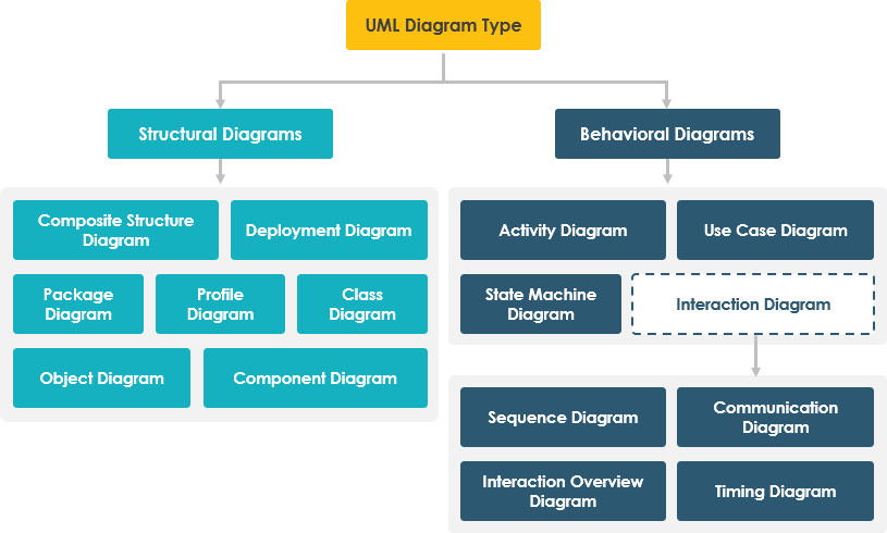
The 14 UML 2 Diagram Types: A Practical Catalog
Diagrams are truly the heart of UML. I categorize them into two families based on what they emphasize:
Structural Diagrams (Static perspective)
-
Show the system’s static structure and relationships across abstraction levels
-
Elements represent meaningful system concepts: abstract, real-world, or implementation-focused
Behavioral Diagrams (Dynamic perspective)
-
Capture dynamic behavior as sequences of changes over time
-
Essential for modeling workflows, interactions, and state transitions
Structural Diagrams Deep Dive
Class Diagrams
The most widely used UML diagram in object-oriented development. Class diagrams describe system objects, their attributes, operations, and relationships. What makes them particularly valuable is their direct mapping to object-oriented programming languages.
My experience: I rely on class diagrams during design phases to establish clear contracts between components. They serve as both documentation and a communication tool with development teams.

Object Diagrams
These show concrete instances of classes at a specific moment—essentially a “snapshot” of the system state. While class diagrams represent abstract models, object diagrams illustrate actual data structures in action.
Practical use: I find object diagrams helpful for debugging complex relationships or demonstrating specific scenarios to stakeholders who prefer concrete examples over abstract models.

Component Diagrams
These describe the static implementation view, focusing on physical components like libraries, files, and executables. They’re particularly useful for understanding system modularity and dependency management.

Deployment Diagrams
System engineers will appreciate deployment diagrams, which model how software components map to hardware nodes. They’re essential for infrastructure planning and understanding runtime environments.

Package Diagrams
These organize model elements into groups (packages) and show dependencies between them. I use package diagrams to manage large systems by creating logical boundaries and controlling visibility.

Composite Structure Diagrams
A UML 2.0 addition that shows the internal structure of classes and their collaborations. These are invaluable for modeling complex components with intricate internal relationships.

Profile Diagrams
These enable creation of domain-specific stereotypes and constraints. I’ve found profile diagrams particularly useful when extending UML for specialized domains like healthcare or finance.

Behavioral Diagrams Deep Dive
Use Case Diagrams
These capture system functionality from a user perspective, showing actors and their interactions with use cases. While not ideal for code generation, they’re powerful planning instruments used throughout the development cycle.
My approach: I start every project with use case diagrams to align stakeholders on scope and functionality before diving into technical design.

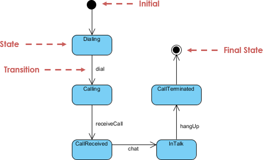
State Machine Diagrams
These model the lifecycle of objects, showing states, transitions, and events. Developed by David Harel, they’re essential for systems with complex state-dependent behavior.
Activity Diagrams
These describe workflows and business processes, modeling control flow between activities. I use them extensively for documenting business rules and operational procedures.

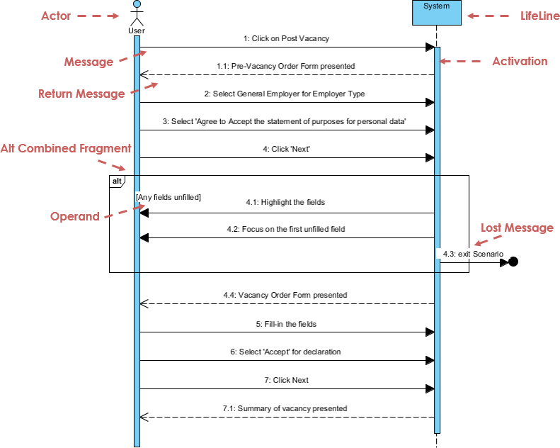
Sequence Diagrams
These model object interactions over time, showing message sequences in specific scenarios. They’re my go-to for understanding complex collaboration patterns.
Communication Diagrams
Similar to sequence diagrams but emphasizing object relationships over time sequencing. I find them useful when the focus is on structural relationships rather than temporal order.

Interaction Overview Diagrams
These provide high-level overviews of interaction flows, using activity diagram notation with interaction nodes. They help manage complexity in large interaction models.

Timing Diagrams
These show object behavior over specific time periods, with time progressing left-to-right. They’re specialized but invaluable for real-time or performance-critical systems.

UML’s Enduring Value: Unified and Open
After years of working with various modeling approaches, I’ve come to appreciate two key aspects of UML’s “unified” nature:
-
Standardization: UML effectively eliminates inconsequential differences between earlier modeling languages, providing a common foundation for the community
-
Perspective Unification: It bridges different system types (business vs. software), development phases (analysis to implementation), and conceptual approaches
The fact that UML is non-proprietary, open, and built upon semantics from Booch, OMT, OOSE, and other leading methods has facilitated widespread adoption across organizations and tool vendors.
The AI Revolution in UML Modeling: My Hands-On Experience
Applying UML principles in real-world projects can be challenging, especially when balancing detail with agility. Recently, I explored Visual Paradigm’s AI-powered modeling tools, and the experience has been transformative. Here’s what stood out in my evaluation:
Recent AI Feature Additions (March–April 2026)
Visual Paradigm has rolled out specialized AI generators that significantly reduce manual modeling effort:
-
AI Profile Diagram Generator (Late March 2026): Creates UML Profile Diagrams from text descriptions, perfect for defining domain-specific customizations without manual stereotype drawing
-
AI Component Diagram Generator (March 2026): Transforms textual descriptions into structured Component Diagrams, automatically handling interfaces and dependencies
-
Enhanced Deployment Diagrams: The AI Chatbot now produces more precise, context-aware layouts with smarter relationship handling to eliminate unwanted connections
-
Composite Structure Diagram Improvements: Early 2026 updates deliver richer, more stable representations of internal class structures
Key AI Modeling Capabilities I Tested
-
AI Chatbot for Visual Modeler: I used natural language to generate initial Class and Object Diagrams, then refined them through conversational follow-ups. The real-time updates were impressively responsive.
-
AI Use Case Modeling Studio: This automated assistant turned plain-language requirements into complete use case models with actors, relationships, and detailed flows—saving hours of manual diagramming.
-
AI Activity Diagram Generator (Added February 2026): Generated professional Activity Diagrams from text descriptions, with recent updates eliminating “orphan” decision nodes for cleaner workflow visualization.
-
Broad Diagram Support: The AI engine now supports instant generation for Use Case, Class, Sequence, State Machine, Communication, and Package Diagrams, plus non-UML types like ERD, DFD, and C4 models.
Practical Considerations for AI-Powered UML
To leverage these AI features in Visual Paradigm Desktop, I noted these requirements:
-
License Level: Features are generally accessible in Professional Edition or higher
-
Maintenance: Starting January 2026, an active subscription or software maintenance (for perpetual licenses) is required for AI tool access
-
Connectivity: The desktop application must connect to Visual Paradigm Online with projects hosted there to access AI generation servers
Conclusion
My journey through UML’s landscape—from foundational concepts to AI-powered modernization—reinforces my belief in its enduring value. UML remains the most comprehensive visual language for system modeling, offering unparalleled flexibility for both technical and non-technical stakeholders. What excites me most is how AI integration is addressing historical pain points: reducing manual effort, accelerating diagram creation, and making professional modeling accessible to broader teams.
For practitioners considering UML adoption or modernization, my recommendation is clear: embrace the standard’s core principles while leveraging AI tools to handle repetitive modeling tasks. This combination preserves UML’s rigor while dramatically improving productivity. Whether you’re documenting legacy systems, designing new architectures, or facilitating cross-functional collaboration, UML—especially when augmented with intelligent tooling—provides the visual foundation for clearer communication, better design decisions, and more successful system outcomes.
The future of modeling isn’t about replacing human expertise with automation; it’s about amplifying our capabilities. With UML as the standard and AI as the accelerator, we’re entering an era where complex system design can be both rigorous and remarkably efficient.
References
-
Visual Paradigm 18.0 Release: AI-Powered Features: Announcement of the Visual Paradigm 18.0 release featuring deep integration of generative AI across the modeling ecosystem.
-
AI Product Area Updates: Central hub for all AI-related feature updates and announcements from Visual Paradigm.
-
Enhanced AI Activity Diagram Support in Visual Paradigm AI Chatbot: Update detailing improvements to AI-generated Activity Diagrams, including elimination of orphan decision nodes for cleaner workflow visualization.
-
AI Profile Diagram Generator Update: Introduction of AI-powered Profile Diagram generation from text descriptions for domain-specific UML customizations.
-
AI Component Diagram Generator Update: New capability to transform textual descriptions into structured UML Component Diagrams automatically.
-
Enhanced AI Composite Structure Diagram Generation: Improvements to AI-generated Composite Structure Diagrams for richer internal class structure representation.
-
Enhanced AI Deployment Diagram Generation: Context-aware layout improvements for AI-generated Deployment Diagrams with smarter relationship handling.
-
Visual Paradigm Desktop AI Activity Diagram Generation: Guide to generating Activity Diagrams directly within Visual Paradigm Desktop using AI.
-
AI Sequence Diagram Example: ATM Cash Withdrawal: Practical example demonstrating how the AI Chatbot generates Sequence Diagrams from natural language descriptions.
-
AI Diagram Generator Overview: Comprehensive overview of AI-powered diagram generation capabilities across multiple UML and non-UML diagram types.
-
Enhance Design Thinking with New AI Diagram Generation: Article on leveraging AI diagram generation to accelerate design thinking and architectural planning.
-
AI Features Software Maintenance Requirement 2026: Important notice regarding subscription and maintenance requirements for accessing AI-powered tools starting January 2026.
-
Getting Started with AI: Click Start AI: Technical support guide for enabling and using AI features in Visual Paradigm.
-
YouTube: AI Diagram Generation Tutorial: Video tutorial demonstrating AI-powered UML diagram creation workflows.
-
YouTube: AI Use Case Modeling Demo: Video demonstration of AI-assisted Use Case modeling capabilities.
-
YouTube: AI Sequence Diagram Walkthrough: Step-by-step video guide for generating Sequence Diagrams using AI.
-
YouTube: AI Setup and Configuration: Video tutorial on setting up and configuring AI features in Visual Paradigm.