


In the architecture of complex information systems, the integrity of data is the foundation upon which reliability rests. When data moves between processes, external entities, and storage locations, inconsistencies can arise silently, leading to critical failures, reporting errors, and compromised security. Data Flow Diagrams (DFDs) serve as a visual blueprint for understanding how information traverses a system. However, a diagram is only as good as the consistency it enforces. This guide explores the rigorous process of verifying data consistency through detailed DFD analysis, ensuring that every byte entering, processing, and leaving the system remains accurate and trustworthy.
Data consistency is not merely a technical checkbox; it is a structural necessity. It involves ensuring that data definitions, transformations, and storage mechanisms align perfectly across all layers of a system design. Without this alignment, processes may operate on stale or incorrect information. By analyzing the flow of data, architects and analysts can identify discrepancies before a single line of code is written. This process requires a deep understanding of system dynamics, logical structures, and the relationships between various components.
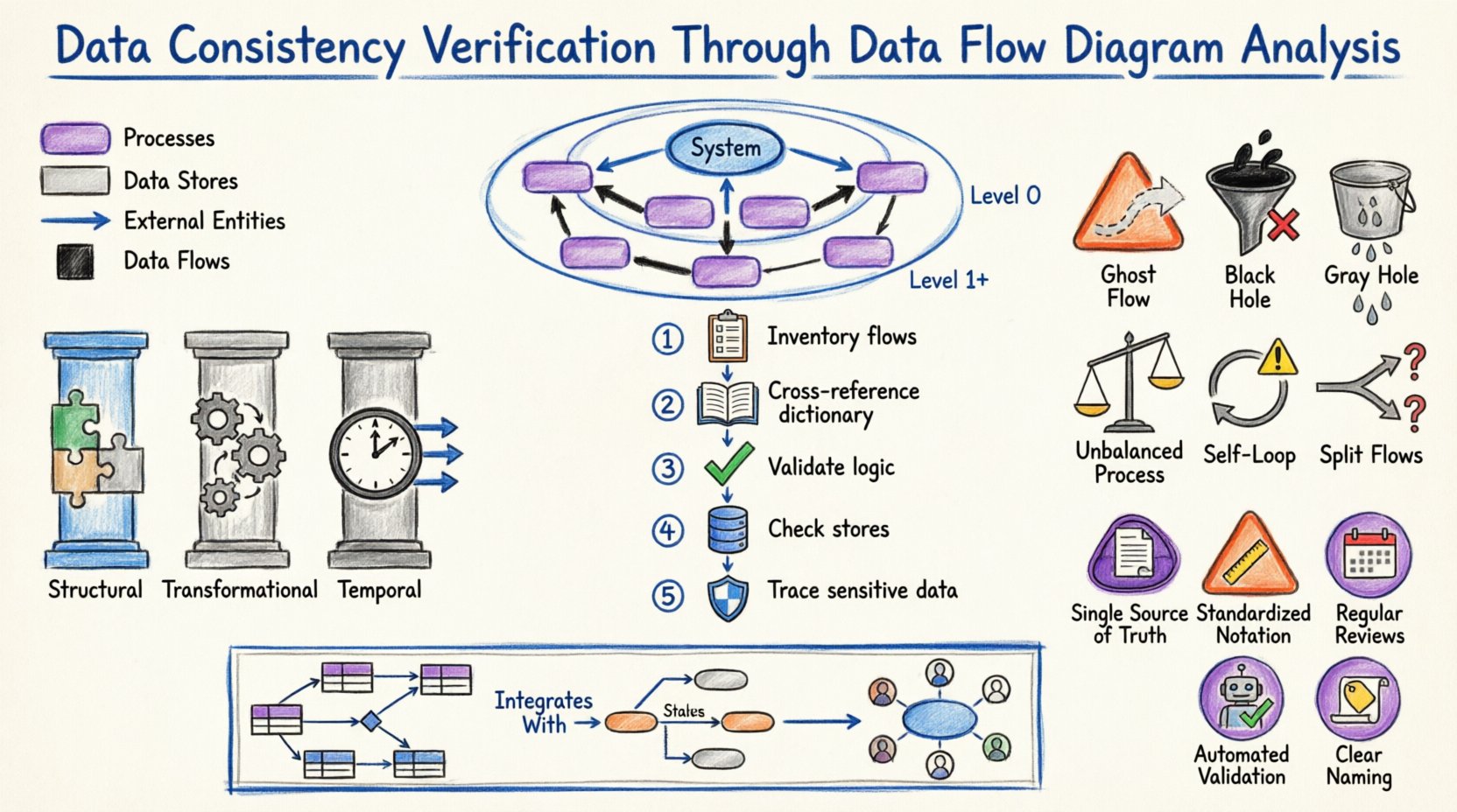
🛡️ Understanding Data Consistency in System Design
Before diving into the mechanics of verification, it is essential to define what data consistency means within the context of system design. It is not a binary state of “correct” or “incorrect.” Instead, it is a spectrum of alignment between different representations of the same information.
📊 Defining the Core Pillars
Consistency in system design generally falls into three primary categories:
- Structural Consistency: This refers to the alignment of data structures. If a process expects a “Customer ID” as an integer, the data store providing that ID must not return a string.
- Transformational Consistency: This ensures that the logic applied to data during processing remains uniform. A calculation performed in Process A should yield the same result as a similar calculation in Process B, assuming identical inputs.
- Temporal Consistency: This addresses the timing of data updates. Information should be available when needed, and updates should propagate through the system without causing race conditions or stale reads.
DFDs provide the map for navigating these pillars. By tracing the paths of data, analysts can spot where these pillars might crack. For instance, if a data flow enters a process without a corresponding output flow, the data has vanished, indicating a structural or logical error.
🔄 The Role of DFD in Ensuring Integrity
Data Flow Diagrams are more than just drawings; they are formal specifications of information movement. In the context of verification, a DFD acts as a contract between the requirements and the implementation. It dictates where data comes from, where it goes, and how it changes.
🔎 Key Components and Their Impact
To verify consistency, one must understand the specific role each component plays:
- External Entities: These are the sources and destinations of data outside the system boundary. Verification here involves ensuring that the system correctly interprets inputs from users, other systems, or hardware devices.
- Processes: These transform input data into output data. Consistency checks here focus on the logic and the data dictionary definitions. Does the process actually modify the data as described?
- Data Stores: These are repositories where data rests. Consistency involves ensuring that the schema matches the flows entering and leaving the store. Is data being written to a store that expects a different format?
- Data Flows: These are the pipes carrying data. Every flow must have a defined source and destination. Unidentified flows are a primary source of inconsistency.
📉 Levels of DFD and Consistency Checks
DFDs are typically hierarchical. Moving from high-level abstractions to detailed specifics allows for layered verification. Each level requires a different type of consistency check.
🏁 Context Level (Level 0)
The Context Diagram represents the entire system as a single process. It shows interactions with external entities. Verification at this level focuses on the boundary. Are all external entities accounted for? Do all major data inputs and outputs cross the boundary?
Checklist for Context Level:
- Is there exactly one process representing the system?
- Are all external entities correctly labeled?
- Do all data flows crossing the boundary have clear definitions?
🏗️ Level 0 (Top Level Decomposition)
At this stage, the single process is broken down into major sub-processes. This is where balancing becomes critical. The inputs and outputs of the sub-processes combined must equal the inputs and outputs of the parent context process.
If the Context Diagram shows an input of “Order Request,” the Level 0 diagram must show “Order Request” flowing into at least one of the top-level processes. If this data disappears, it is a black hole—a critical consistency error.
🧩 Level 1 and Below (Detailed Decomposition)
As diagrams break down further, the focus shifts to logical flow. Do the data flows match the granularity of the processes? Is data being passed between processes that should be stored first? Is there unnecessary coupling between modules?
📝 Step-by-Step Verification Protocol
Verifying consistency is a systematic activity. It requires a methodical approach to ensure no detail is overlooked. The following protocol outlines the standard procedure for analysis.
1️⃣ Inventory All Flows
Begin by listing every data flow present in the diagram. Create a master list that includes the name of the flow, the source, and the destination. This inventory serves as the baseline for all subsequent checks.
2️⃣ Cross-Reference with Data Dictionaries
A Data Dictionary defines the structure, type, and constraints of every data element. Each data flow in the DFD must have a corresponding entry in the dictionary.
- Match Names: Ensure the flow name in the diagram matches the dictionary term exactly.
- Match Types: Verify that the data type (e.g., String, Integer, Date) is consistent across the diagram and the dictionary.
- Match Constraints: Check if validation rules (e.g., “Must be positive”) are applied consistently.
3️⃣ Validate Process Logic
For every process node, verify the transformation logic. Does the process produce all expected outputs given the inputs? Are there any outputs that appear without a logical cause? This step often requires reviewing pseudocode or business rules associated with the process.
4️⃣ Check Data Store Alignment
Every data flow entering a data store must match the schema of that store. Conversely, every flow leaving a store must represent data that actually exists within it. Verify that read and write operations are balanced.
5️⃣ Trace the Path of Sensitive Data
Identify flows containing sensitive information (PII, financial data). Ensure that consistency checks include security protocols. If data is encrypted at the source, is it decrypted at the destination? Are there any unencrypted flows that should be secure?
⚠️ Common Inconsistencies and Patterns
Despite careful planning, inconsistencies creep in. Recognizing common patterns of error allows for faster detection during analysis. The table below outlines frequent issues and their implications.
| Pattern Name | Description | Consistency Impact |
|---|---|---|
| Ghost Flow | A data flow with no source or destination. | Breaks the continuity of data; causes system errors. |
| Black Hole | A process with inputs but no outputs. | Data is lost; the system state becomes undefined. |
| Gray Hole | A process where the output is less than the sum of inputs, or the logic doesn’t account for all inputs. | Partial data loss or incorrect aggregation. |
| Unbalanced Process | A child process has different inputs/outputs than the parent process it decomposes. | Breaks the hierarchy; requirements are not met. |
| Self-Looping Data | A data flow that feeds back into the same process without a data store. | Indicates infinite loops or lack of state management. |
| Split Flows | Data splits into multiple paths without a decision node. | Unclear routing; potential data duplication. |
🔗 Data Dictionary Integration
The Data Dictionary is the single source of truth for data definitions. Without a dictionary, DFDs are ambiguous. Verification is incomplete without cross-referencing the diagram against this repository.
📋 The Synchronization Requirement
When a DFD is updated, the Data Dictionary must be updated simultaneously. A mismatch here is a form of inconsistency. For example, if a field is renamed in the dictionary from “User_Name” to “Username,” the DFD must reflect this change immediately. Failure to do so creates a disconnect between the design document and the implementation specification.
📌 Metadata Consistency
Beyond names and types, metadata must be consistent. This includes:
- Units of Measure: Is currency in USD or EUR? Is weight in kg or lbs? This must be consistent across all flows involving that data.
- Encoding Standards: Is text encoded in UTF-8 or ASCII? Inconsistent encoding leads to data corruption.
- Time Zones: Does the system store time in UTC or local time? Flows involving timestamps must agree on the standard.
🧭 Logical vs. Physical Consistency
A common pitfall is conflating logical and physical designs. A Logical DFD shows what the system does, while a Physical DFD shows how it does it. Consistency verification must distinguish between the two.
🧱 Logical Consistency
This focuses on business rules and data integrity. Does the flow make sense from a business perspective? For example, can an order be shipped before payment is authorized? Logical consistency ignores technology and focuses on the flow of value.
💻 Physical Consistency
This focuses on technology constraints. Does the data flow match the network protocols? Is the data format compatible with the database engine? A physical inconsistency might not break the business logic but will cause system failure during deployment.
🔄 Bridging the Gap
When transitioning from Logical to Physical, new flows often appear (e.g., error logs, audit trails). These must be added to the diagram to maintain consistency. If the physical implementation adds a step that the logical diagram did not account for, the logical diagram is now inconsistent with reality.
🔎 Cross-Reference with Entity Relationship Models
DFDs describe movement, while Entity Relationship Diagrams (ERDs) describe structure. To ensure total consistency, these two diagrams must align.
🗺️ The Mapping Exercise
For every data store in the DFD, there should be a corresponding entity set in the ERD. For every data flow, there should be a relationship or attribute that justifies the movement.
- Cardinality Check: If a DFD shows a many-to-one flow into a process, the ERD should reflect the corresponding relationship cardinality.
- Key Consistency: Primary keys used to identify records in the ERD must be the same keys used in the data flows to reference those records.
Discrepancies here often lead to performance bottlenecks or referential integrity violations during runtime. A rigorous review compares the schema of the data stores against the ERD entities.
🛠️ Maintenance and Lifecycle Management
Consistency is not a one-time achievement. It is a continuous state that must be maintained throughout the system lifecycle. As requirements change, diagrams must evolve.
📂 Version Control for Diagrams
Just as code requires version control, DFDs require it too. Changes to a diagram should be tracked. This allows teams to audit when and why consistency was broken or restored. A change log should accompany every update to the DFD.
🔄 Regression Testing
When a diagram is updated, the consistency checks should be re-run. This is akin to regression testing in software development. Did the new flow introduce a black hole? Did the new process break the balancing with the parent context? Automated tools can assist in this, but manual review is often necessary for complex logic.
👥 Stakeholder Alignment
Consistency also involves people. Business stakeholders must agree on the data definitions. If the business defines “Active User” as someone who logged in last week, but the technical team defines it as someone who logged in last month, the DFD will reflect the technical definition, leading to business reporting errors. Regular alignment meetings are essential.
📈 Audit Trails and Traceability
In regulated industries, traceability is a legal requirement. Every piece of data must be traceable from its source to its final destination. DFDs are the primary tool for establishing this traceability.
🔖 Tagging Flows
Each data flow should be tagged with metadata indicating its origin and purpose. This helps in auditing. If a data breach occurs, analysts can trace the flow on the diagram to identify where the vulnerability might have existed.
🔗 Impact Analysis
If a change is proposed to a data store, the DFD allows for impact analysis. By tracing the flows connected to that store, the team can identify all processes that will be affected. This prevents accidental inconsistencies introduced by unilateral changes.
🎯 Best Practices for Maintenance
To sustain consistency over time, adhere to these best practices:
- Single Source of Truth: Maintain one master repository for DFDs. Do not allow multiple versions to exist in different locations.
- Standardized Notation: Use a consistent notation (e.g., Gane & Sarson or Yourdon & Coad) throughout the entire documentation suite. Mixing notations creates confusion.
- Regular Reviews: Schedule quarterly reviews of the DFDs against the current system state. Systems drift over time; diagrams must catch up.
- Automated Validation: Where possible, use modeling tools that validate consistency rules automatically (e.g., preventing unbalanced processes).
- Clear Naming Conventions: Adopt strict naming conventions for processes and flows. Ambiguous names are a breeding ground for inconsistency.
🌐 Integration with Other Methodologies
DFDs do not exist in a vacuum. They are part of a larger ecosystem of design artifacts.
📋 State Transition Diagrams
While DFDs show data movement, State Transition Diagrams show state changes. Ensure that the data flows triggering a state change match the conditions defined in the state diagram. If a “Login Attempt” flow triggers a state change, the logic must be consistent across both diagrams.
📊 Use Case Diagrams
Use Cases describe interactions from a user perspective. DFDs describe the internal mechanics. Every use case should map to at least one process in the DFD. If a use case has no corresponding process, the requirement is not met. If a process has no use case, it may be dead code.
🏁 Final Thoughts on Verification
Ensuring data consistency through DFD analysis is a discipline that requires patience and attention to detail. It is not about finding bugs; it is about building a robust foundation. By rigorously checking balances, cross-referencing dictionaries, and maintaining alignment between logical and physical views, systems analysts can prevent errors before they manifest in production.
The effort invested in this verification pays dividends in system stability and reduced maintenance costs. A consistent design is a design that understands its own data. As systems grow in complexity, the reliance on clear, consistent diagrams becomes the primary defense against chaos. Adhering to these principles ensures that the flow of information remains as reliable as the business logic driving it.