


Successful project transitions rely heavily on clarity, precision, and comprehensive documentation. When a development team hands off a system to operations or a maintenance group, the risk of miscommunication increases significantly. Without clear visual aids, the intricate pathways of data within a system often become obscured, leading to errors during maintenance and support. Data Flow Diagrams (DFDs) serve as a critical component in this process, offering a visual representation of how information moves through a system. This guide explores the essential elements of creating project handoff documentation centered around effective Data Flow Diagrams.
Understanding the Role of DFDs in Project Handoffs 🧠
Data Flow Diagrams are not merely technical drawings; they are the blueprint for system logic. During a project handoff, stakeholders need to understand not just what the system does, but how it processes information. A well-constructed DFD provides a high-level view of the system architecture without getting bogged down in code-level details. This abstraction is vital for operations teams who may not be involved in the original development but must manage the system’s lifecycle.
In the context of a handoff, the documentation must bridge the gap between the build team and the support team. The DFD acts as a common language. It allows engineers to discuss data sources, processing steps, and storage locations without ambiguity. This shared understanding reduces the time spent on clarifying basic system functions and allows the support team to focus on stability and performance.
Why DFDs Are Essential for Maintenance 🛠️
Maintenance often involves troubleshooting issues that stem from data bottlenecks or processing errors. When a system slows down or produces incorrect outputs, the DFD helps isolate the problem area. Instead of searching through logs or code, a maintainer can trace the data path visually.
Visual Traceability: You can follow a specific data element from entry to storage.
Process Clarity: It defines exactly what transformation occurs at each step.
Dependency Mapping: It shows which processes rely on which data stores.
Boundary Definition: It clearly marks what is inside the system versus external entities.
Core Components of a DFD for Handoffs 🔧
To ensure the handoff documentation is effective, the DFD must adhere to standard notations. While various notations exist, consistency is the most important factor. For a handoff package, the diagram must be annotated clearly so that any team member can interpret it without prior context.
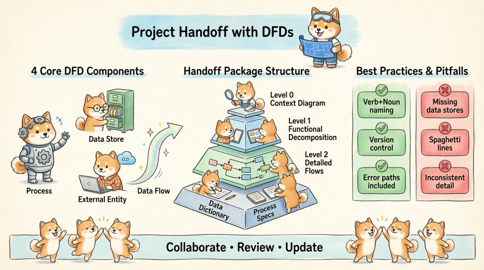
The four primary symbols used in DFDs are processes, data stores, external entities, and data flows. Each plays a distinct role in defining the system’s behavior.
Component | Symbol Representation | Function in Handoff Documentation |
|---|---|---|
Process | Circle or Rounded Rectangle | Represents an action that transforms input data into output data. |
Data Store | Open Rectangle or Parallel Lines | Indicates where data is saved or retrieved within the system. |
External Entity | Square or Rectangle | Represents users, systems, or organizations outside the boundary. |
Data Flow | Arrow | Shows the direction and name of data moving between components. |
Annotating the Diagrams for Clarity 📝
Visuals alone are often insufficient for complex systems. Annotations provide the necessary context. Every process should have a unique identifier and a descriptive name. Every data flow should be labeled to indicate the type of information moving.
Process Naming: Use verb-noun pairs (e.g., “Validate User Input”).
Data Flow Labels: Specify the data package (e.g., “Login Credentials”).
Data Store IDs: Use consistent naming conventions (e.g., “DS-01-UserDB”).
Versioning: Clearly state the diagram version and date.
Preparing the Handoff Package 📦
The handoff documentation is a collection of artifacts. The DFDs are the centerpiece, but they must be supported by a structured package. This package ensures that the receiving team has all the resources they need to take over the system without interruption.
Structure of the Documentation Package 📚
A robust handoff package should be organized logically. It should allow a new engineer to find information quickly. The following structure is recommended for technical handoffs:
Executive Summary: A brief overview of the system’s purpose and scope.
Context Diagram (Level 0): The highest-level view showing the system as one process interacting with external entities.
Functional Decomposition (Level 1): Breaking down the main process into major sub-processes.
Detailed Flows (Level 2): Further breakdown for complex sub-processes.
Data Dictionary: Definitions of all data elements used in the diagrams.
Process Specifications: Detailed logic for each process node.
Ensuring Consistency Across Artifacts 🔄
Inconsistencies between the diagram and the text can cause significant confusion. If the Level 1 diagram shows five processes, the accompanying text must describe exactly those five. Cross-referencing is key. Every process ID in the diagram should appear in the text, and vice versa.
Consistency extends to the naming conventions as well. Do not use “Customer Table” in one document and “Client DB” in another. Establish a naming standard at the start of the project and enforce it throughout.
Creating the DFDs Step-by-Step 📐
Constructing the diagrams requires a systematic approach. Rushing this step often leads to missing data flows or unclear boundaries. The process should move from the general to the specific.
Step 1: Define the System Boundary 🚧
The first step is to decide what is inside the system and what is outside. This boundary determines the scope of the handoff. Anything that provides input or receives output is an External Entity. Anything that stores or processes data internally belongs to the system.
Identify all users and external systems.
Define the system’s name.
Draw the boundary line.
Step 2: Map the Context Diagram (Level 0) 🌍
The context diagram provides the “big picture.” It represents the entire system as a single process. This is crucial for the handoff because it establishes the primary interaction points.
Place the system in the center as a single process.
Draw External Entities around the perimeter.
Connect entities to the system with arrows showing data input and output.
Label all data flows clearly.
Step 3: Decompose into Level 1 Diagrams 🧩
Once the context is clear, break the central process into major sub-processes. These represent the main functional areas of the system. For example, if the system is an order management platform, the Level 1 processes might be “Receive Order,” “Process Payment,” and “Update Inventory.”
Ensure that every data flow entering the Level 0 process is accounted for in the Level 1 diagram. This is a common point of failure in handoffs where data disappears between levels.
Step 4: Refine with Level 2 Diagrams 🔍
Complex sub-processes from Level 1 may need further breakdown. Level 2 diagrams dive deeper into specific logic. This level is particularly important for handoff documentation because it often contains the logic that operations teams need to troubleshoot.
Do not over-complicate Level 2 diagrams. If a process is simple, keep it at Level 1. Only decompose when the logic becomes too complex to understand in a single view.
Documentation Best Practices 📚
Creating the diagrams is only half the battle. The documentation surrounding them must be clear and accessible. Adhering to best practices ensures the handoff is sustainable.
Naming Conventions and Standards 🏷️
Consistency reduces cognitive load for the receiving team. Adopt a standard naming convention for all objects in the diagrams and documentation.
Processes: Verb + Noun (e.g., “Calculate Tax”).
Data Stores: Noun + Type (e.g., “Order_Log”).
Data Flows: Noun Phrase (e.g., “Tax Calculation Result”).
Document these conventions in the Data Dictionary section of the handoff package. This serves as a reference guide for anyone reading the diagrams later.
Handling Complexity and Exceptions ⚠️
Real-world systems have exceptions and error paths. A DFD that only shows the happy path is incomplete. Handoff documentation must account for error handling and alternative flows.
Include data flows for error messages returning to the user.
Mark data flows that trigger logging or auditing.
Indicate where data is discarded or archived.
If a process has multiple outcomes, ensure the DFD reflects the conditions that lead to each outcome. This might require additional notes or legend keys.
Common Pitfalls to Avoid 🚫
Even experienced teams can stumble when preparing handoff documentation. Recognizing common mistakes helps ensure the quality of the deliverables.
Pitfall 1: Missing Data Stores
Data must go somewhere. If a process generates data but no data store receives it, the system loses information. This is a critical flaw in handoff documentation. Review every data flow to ensure it either goes to another process or a data store.
Pitfall 2: Spaghetti Connections
Avoid crossing lines excessively. While not a logical error, messy diagrams are hard to read. Use bends and straight lines to keep the layout clean. If the diagram becomes too crowded, consider splitting it into multiple views.
Pitfall 3: Inconsistent Granularity
Do not mix high-level and low-level details in the same diagram. If one process is described in a single step, do not decompose a neighbor into five steps unless necessary. Keep the level of detail consistent within a single diagram.
Pitfall 4: Ignoring Data Security
Handoff documentation often overlooks security flows. If sensitive data is transmitted, indicate encryption or security protocols in the data flow labels. This informs the operations team about compliance requirements.
Collaboration and Review 👥
Documentation is not a solo activity. The handoff package should be reviewed by multiple stakeholders before the transition occurs. This ensures that the diagrams match the actual system behavior.
Validation with the Development Team 🛡️
The developers who built the system should verify the DFDs. They can confirm that the logic matches the implementation. If a data flow is missing, they can identify it early. This step prevents surprises during the operational phase.
Validation with the Operations Team 🔧
The team that will maintain the system should also review the diagrams. They can ask questions about data retention, backup procedures, and monitoring points. Their feedback helps tailor the documentation to their workflow.
Maintenance and Updates 🔁
A handoff document is not static. Systems evolve, and the documentation must evolve with them. Establish a process for updating the DFDs when changes occur.
Version Control for Diagrams 📂
Keep a history of diagram versions. When a change is made, update the version number and the date. This allows the team to track how the system has changed over time.
Integrating with Change Management 🔄
Link diagram updates to the change management process. Whenever a change request is approved, the relevant DFD should be updated before the change is deployed. This keeps the documentation synchronized with the live system.
Accessibility and Storage 📁
Ensure the diagrams are stored in a central, accessible location. The receiving team should have immediate access to the documentation. Avoid storing files on local drives that might be lost during personnel changes.
Conclusion on Effective Handoffs 🏁
Project handoffs are critical junctures in the system lifecycle. The quality of the handoff determines the stability of the system in the future. Data Flow Diagrams provide the visual clarity needed to transfer knowledge effectively. By following structured processes, adhering to standards, and involving the receiving team, organizations can ensure smooth transitions.
Focusing on the details of the DFDs—such as naming, granularity, and completeness—creates a foundation for long-term maintenance. The effort invested in creating high-quality documentation pays dividends when the system requires troubleshooting or expansion. A clear visual representation of data movement is an asset that outlasts any single codebase or developer.
Remember that the goal is clarity and sustainability. When the handoff package is comprehensive and accurate, the operations team can perform their duties with confidence. This reduces downtime and improves the overall reliability of the software solution.