

From Abstract Geometry to Enterprise Architecture: Mastering Inheritance with Real-World Context
When developers and architects first encounter inheritance in Unified Modeling Language (UML), they often get stuck in the weeds of syntax: “Should the arrow point up or down?” “Is it a solid line or a dashed one?” “Why does my Visual Paradigm diagram look different from the textbook example?”
However, in the high-stakes environment of enterprise software development, these visual nuances are secondary to the semantic truth they represent. Whether you are building a financial risk engine, an e-commerce inventory system, or a healthcare data platform, the core concept remains the same: specialization.
Let’s explore a classic example—the Shapes Hierarchy—but strip away the academic abstraction and look at how this pattern solves actual operational problems in the field. We will also decode why the same logical relationship can appear in two different visual styles without losing its meaning.
The Real-World Problem: Reducing Code Duplication
Imagine you are an architect for a large-scale Insurance Claims Processing System. The system needs to calculate premiums based on the type of asset being insured. You have three distinct asset types:
- Car: Has a make, model, and year.
- House: Has square footage, number of rooms, and construction year.
- Boat: Has length, engine type, and hull material.
Without inheritance, your code might look like a nightmare of repetition. Every class would need a method called calculateRisk(), but the logic would differ slightly. More importantly, every class would need to store common attributes like id, ownerName, and purchaseDate.
This leads to the Base Class (or Parent Class) concept. You create a generic Asset class that holds the common data. The specific classes (Car, House, Boat) then inherit this structure, adding only their unique properties. This is the essence of the Shapes hierarchy, translated from geometry to business logic.
Visualizing the Hierarchy: The “Shapes” Example in Enterprise Terms
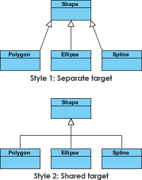
Consider the image provided from Visual Paradigm, which displays an inheritance hierarchy involving Shapes. While the diagram uses geometric terms, the pattern is identical to the Asset example above.
In this scenario, you have a generic Shape class. It defines the fundamental contract for all shapes: it has an area, a perimeter, and a method to draw(). Below it, you have specialized classes like Circle, Rectangle, and Triangle.
Why this matters: If you are building a CAD (Computer-Aided Design) tool for an engineering firm, or a rendering engine for a video game, you don’t want to write the “draw” logic from scratch for every single object type. Inheritance allows the Shape parent to define the interface, while the children implement the specific behavior.
Two Styles, One Truth: Decoding the Connector Variations
The image you provided illustrates a critical lesson for any technical writer or architect: semantics over syntax. The figure shows two different ways to draw the inheritance relationship:
- The Standard UML Style: A solid line with a hollow, unfilled triangle arrowhead pointing to the parent class.
- The Alternative Style: A different visual representation (often seen in older notations or specific tool configurations) that might use a different line weight or arrow style, yet points to the same relationship.
In the context of Visual Paradigm and the tech-posts.com audience, it is vital to understand that these connectors are semantically equivalent.
Whether the line is thick or thin, or the arrow is stylized differently, the logical meaning is identical: Child “is-a” Parent.
This distinction is often a source of confusion for junior developers. They might think, “This diagram looks wrong because the arrow is dashed instead of solid.” In reality, the diagram is correct. The tool is simply allowing flexibility in presentation while maintaining strict logical consistency.
Operational Scenarios: When to Use Inheritance
Before you open Visual Paradigm and start drawing lines, ask yourself: Does this relationship represent a true “is-a” relationship?
Scenario A: The Right Fit (The “Is-A” Test)
Context: A Logistics Management System.
Use Case: You have a class Vehicle and a subclass Truck. A Truck is a Vehicle. A Truck inherits the ability to move() and refuel(), but adds specific methods like loadCargo().
Outcome: You can pass any Vehicle object to a function expecting a Vehicle, and it will accept a Truck without errors. This polymorphism is the power of inheritance.
Scenario B: The Wrong Fit (The “Has-A” Trap)
Context: A Banking Application.
Use Case: You have a BankAccount and a TransactionHistory.
Mistake: A Transaction History is not a Bank Account. It has a Bank Account, or it belongs to one. If you try to model this as an inheritance hierarchy, you will run into problems. You cannot treat a TransactionHistory object as a BankAccount.
Correction: Use Composition or Aggregation instead. The BankAccount should hold a reference to a list of TransactionHistory objects.
Best Practices for Architecting Inheritance Hierarchies
When you are using Visual Paradigm to model your system, keep these industry best practices in mind to ensure your diagrams remain maintainable and your code remains robust.
- Keep the Hierarchy Flat: A deep inheritance tree (e.g.,
Vehicle->MotorVehicle->Truck->HeavyDutyTruck->FireTruck) is often a smell code. It makes the system brittle. If you change theMotorVehicleclass, you break everything below it. Aim for 2-3 levels of depth maximum. - Abstract Base Classes: In your UML diagrams, mark classes that are meant only to be inherited as Abstract. In Visual Paradigm, you can denote this with the {abstract} stereotype. This tells the development team: “Do not instantiate this directly; you must create a specialized version.”
- Consistency is Key: Since the image shows that different visual styles are equivalent, choose one standard for your entire team. If your team agrees on the “Solid Line with Hollow Triangle” style, stick to it. Don’t mix styles in the same diagram unless you are explicitly comparing them for educational purposes.
Conclusion: The Power of Semantic Clarity
The Shapes inheritance example is more than just a geometry lesson; it is a blueprint for organizing complex enterprise systems. By understanding that the visual representation (the connector style) is merely a vehicle for the underlying logic, you can focus on what truly matters: building a system that is scalable, maintainable, and logically sound.
Whether you are drawing a diagram for a new microservices architecture or refactoring a legacy monolith, remember that the goal is not to draw pretty lines. The goal is to clearly communicate that Circle is a Shape, and Truck is a Vehicle, ensuring that your code reflects the reality of the business domain.
Next time you open Visual Paradigm, look past the specific line style. Look at the relationship. That is where the real value lies.