
BPMN and UML activity diagrams can both show actions, decisions, and parallel paths. The key difference is what they are designed to explain: BPMN models business processes across participants; a UML activity diagram models the flow of behavior within a system or software design. Choose based on the question your diagram needs to answer—not just which symbols look familiar.
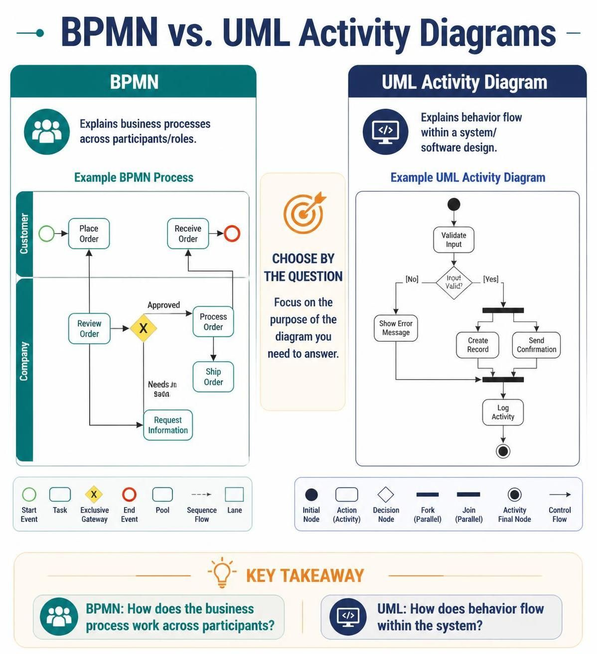
The short version
| If you need to show… | Use… | Why |
|---|---|---|
| How work moves across people, teams, organizations, or systems | BPMN | It has process-focused elements for participants, handoffs, events, and message flows. |
| How a system, service, or component performs a behavior | UML activity diagram | It fits naturally into UML’s broader toolkit for describing software behavior and design. |
| Both the operational process and the software behind it | Both | They describe different views; link related diagrams with shared names or identifiers. |
Where BPMN works best
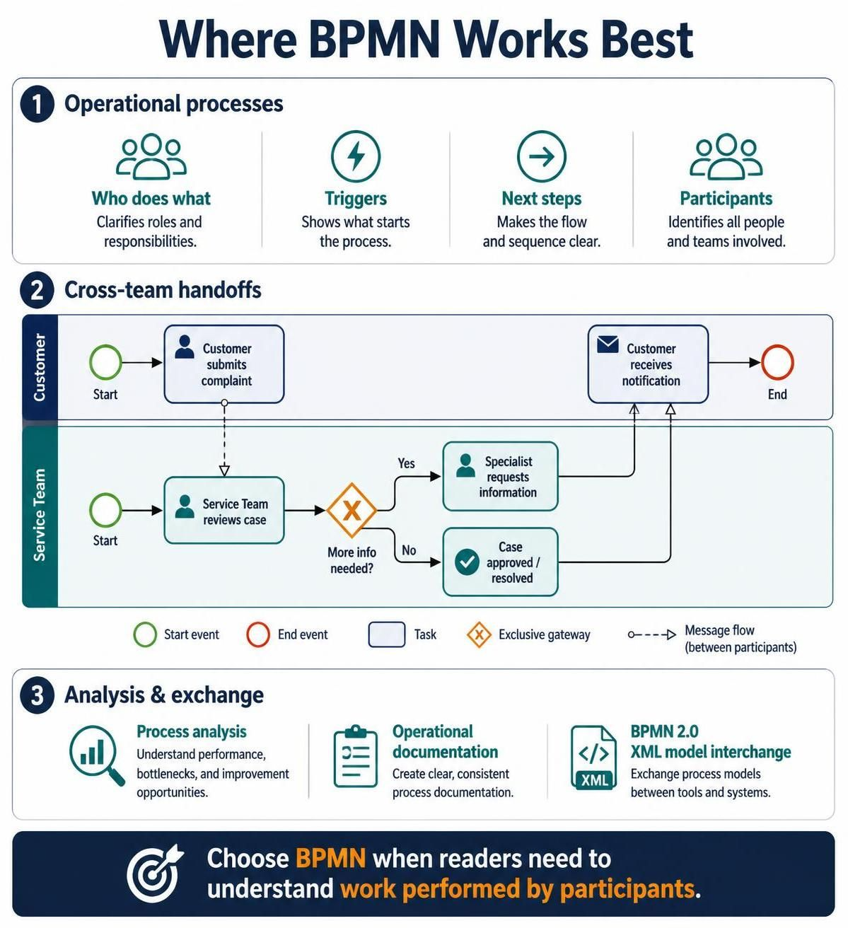
Use BPMN when the subject is an operational process: who does what, what triggers work, where it goes next, and how it moves between participants. It is especially useful when a process crosses organizational boundaries or includes approvals, waiting, messages, exceptions, and alternate paths.
For example, a customer complaint process might show a customer submitting a case, a service team reviewing it, a specialist requesting more information, and a notification going back to the customer. BPMN’s pools, lanes, events, tasks, gateways, and message flows help make those responsibilities and exchanges explicit.
BPMN is also a strong choice when the diagram needs to support process analysis, operational documentation, or exchange between tools. BPMN 2.0 defines both notation rules and an XML format for model interchange.
Choose BPMN when readers need to understand the process as work performed by participants. It is often a better fit for business analysts, process owners, operations teams, and stakeholders reviewing responsibilities or handoffs.
Where UML activity diagrams work best
Use a UML activity diagram when you are describing behavior inside a software system, service, or component. It can show a sequence of actions, decisions, loops, and concurrent work without turning the diagram into an organization-wide operating model.
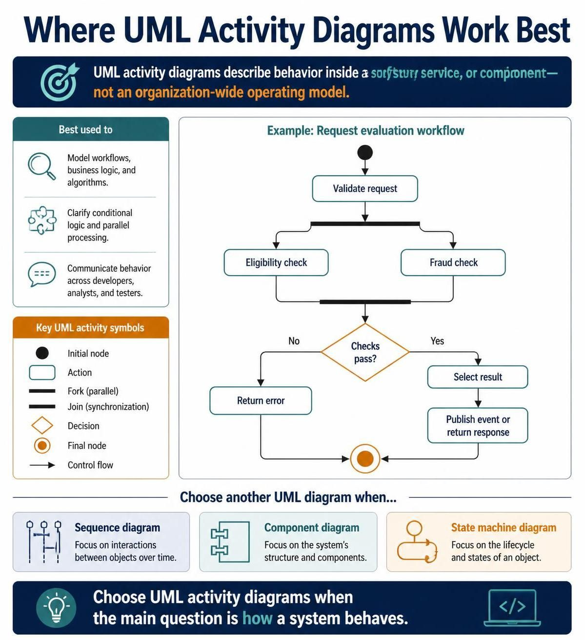
For example, a service might validate a request, run eligibility and fraud checks in parallel, select a result based on the checks, then publish an event or return an error. An activity diagram can make that control flow clear for developers, architects, and engineering teams. UML offers other diagram types—such as sequence, component, and state machine diagrams—when the design question involves interactions, structure, or lifecycle states instead.
Choose UML when the main question is how a system behaves. It is particularly useful in software design discussions where the workflow is bounded to an application or component rather than spanning an entire business operation.
The practical differences
| Dimension | BPMN | UML activity diagram |
|---|---|---|
| Primary focus | End-to-end business or operational process | Behavior or control flow within a system |
| Typical participants | People, teams, organizations, and systems | Actions and flows in a modeled system or design |
| Handoffs and communication | Explicit process concepts for participants and message flows | Can show flow, but is not centered on cross-participant business choreography |
| Broader modeling context | Dedicated to process modeling | One diagram type within a wider software-modeling language |
| Common readers | Process analysts, operations, business stakeholders | Developers, architects, engineering teams |
These are tendencies, not rigid audience rules. Technical teams may need BPMN for operational workflows, and business stakeholders may understand a simple UML activity diagram. The deciding factor is the model’s purpose and scope.
Example: one service, two diagrams
Imagine an online order that requires inventory confirmation and payment authorization.
A BPMN diagram could show the end-to-end process: the customer submits an order, the commerce team or system checks availability, a payment provider authorizes payment, and the customer receives confirmation or an exception notice. It can make participant boundaries and operational handoffs visible.
A UML activity diagram could zoom into the order service’s behavior: validate the request, launch inventory and payment checks, combine their results, then confirm the order or return a failure. It focuses on what the software does, rather than who owns each operational step.
The diagrams complement each other: one explains the process across participants; the other details behavior inside a system.
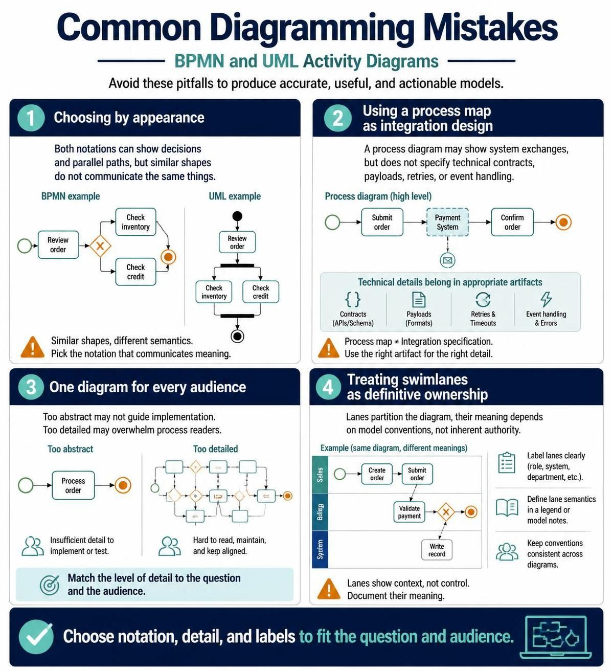
Common mistakes
-
Choosing by appearance. Both notations can show decisions and parallel paths, but similar-looking shapes do not mean the diagrams communicate the same things.
-
Using a process map as integration design. A process diagram may show where systems exchange information, but that alone does not specify technical contracts, payloads, retries, or event handling. Use appropriate technical artifacts for those details.
-
Trying to make one diagram serve every audience. A single model can become either too abstract to guide implementation or so detailed that process readers cannot follow it.
-
Treating swimlanes as definitive ownership. A lane is a way to partition a diagram; what it represents depends on the model’s conventions. Label lanes clearly and document what they mean.
A simple decision rule
Ask: “Is this diagram about work across participants, or behavior inside a system?”
-
If it is about work, ownership, handoffs, events, and operational outcomes, start with BPMN.
-
If it is about actions, branching, and concurrency within a software system or component, start with a UML activity diagram.
-
If it needs to explain both, create two focused diagrams and connect them with consistent names or identifiers rather than mixing notations into one diagram.
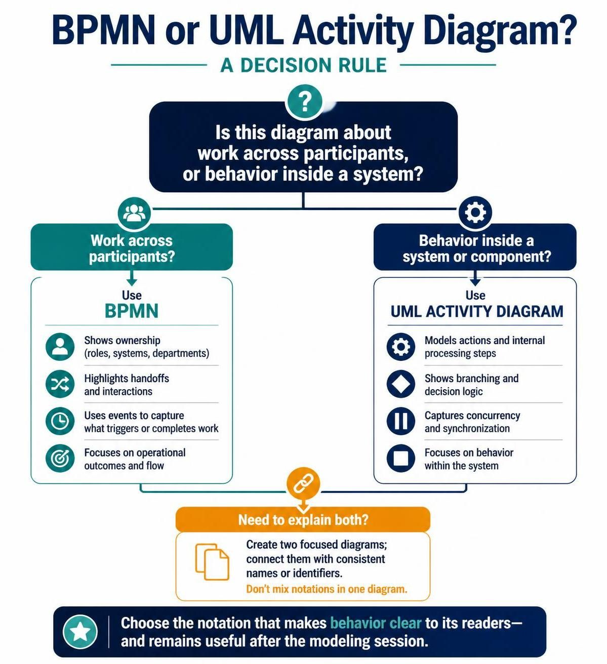
The best notation is the one that makes the relevant behavior clear to its intended readers—and still makes sense when someone uses the diagram after the modeling session is over.
Conclusion
BPMN and UML activity diagrams both clarify workflows, but they answer different questions. Use BPMN to show how work moves between participants, teams, or organizations; use a UML activity diagram to explain how behavior flows within a system or component. Choosing the diagram that matches your audience and scope makes decisions, responsibilities, and handoffs easier to understand.