
Integrating BPMN with User Stories: A Visual Paradigm Tutorial
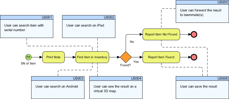
In the realm of software development, the disconnect between business requirements and technical implementation is a frequent source of project failure. User Stories define what the user wants, while Business Process Model and Notation (BPMN) defines how the business operates. By integrating these two concepts, you create a “living documentation” system where high-level requirements are directly traceable to process flows.
This tutorial demonstrates how to effectively map User Stories to a BPMN diagram using Visual Paradigm. We will analyze the provided diagram, which illustrates a workflow for finding an item in inventory, and explain the architectural decisions behind this integration.
1. The Concept: Bridging Process and Requirements
The core philosophy behind this mapping is Traceability. In a traditional waterfall model, requirements and process diagrams are often separate documents. In this modern approach, the User Story is a specific artifact attached to the BPMN model.
When you link a User Story to a process element (like an Activity or a Gateway), you ensure that:
- Clarity: Every business action has a defined functional requirement attached.
- Visualization: Stakeholders can see the process flow (BPMN) alongside the specific user goals (Stories).
- Change Management: If a user requirement changes, you can immediately see which process steps are impacted.
2. Analyzing the Inventory Search Process
Let’s break down the diagram provided. It depicts a scenario where a user attempts to locate an item using its Serial Number (SN).
The Workflow Steps
- Start Event: The process begins with a specific input: SN of Item.
- Print Note: An initial action to prepare for the search.
- Find Item in Inventory: The core business activity. This step is where the logic of the search resides.
- Decision Gateway (Found?): A diamond-shaped element representing a decision point. The flow splits based on whether the item exists in the system.
- End Events: Two possible outcomes:
- Report Item Found: The process terminates successfully if the item is located.
- Report Item Not Found: The process terminates with an error or exception status.
The User Story Mapping
The blue rectangles represent the User Stories (labeled US001 through US006). These are connected to the BPMN elements via dashed lines. This connection is often referred to as a “Traceability Link.”
- US001 (Search with Serial Number): This story is linked to the input of the process and the general activity of finding the item. It defines the functional requirement for the search capability.
- US002 (Search on iPad) & US003 (Search on Android): These stories map to the Find Item in Inventory activity. They represent the Non-Functional Requirements or the specific platform constraints for that step. The system must support searching via these devices.
- US004 (See result on Virtual 3D Map): This story is linked to the success path (Yes). It defines the visualization requirement once the item is found.
- US005 (Forward Result): Linked to the “Report Item Found” path. This implies a social or workflow action—sharing the success.
- US006 (Save Result): Linked to the success path. This is a data persistence requirement.
3. Technical Implementation in Visual Paradigm
To achieve the look and functionality seen in this diagram, Visual Paradigm offers specific features. You do not need to write code to create this; it is a configuration within the modeling tool.
Step-by-Step Modeling Guide
Step 1: Create the BPMN Diagram
Begin by drawing your standard BPMN process using the Palette. Drag and drop the Start Event, Tasks, Gateways, and End Events.
Step 2: Create User Stories
In Visual Paradigm, navigate to the Requirements menu. You can create a “User Story” artifact. Enter the text (e.g., “User can search item with serial number”) and assign it an ID like US001.
Step 3: Add a Custom Layer
This is the key to the visual separation seen in the diagram.
- Right-click on the diagram canvas.
- Select Layers.
- Create a new layer named “User Stories” or “Requirements”.
- Move your User Story artifacts into this layer.
Why do this? It allows you to toggle the visibility of the requirements off during stakeholder meetings if you only want to show the process flow.
Step 4: Establish Traceability
Select the User Story element. Look for the Traceability or Link option in the properties or context menu. Select the target BPMN element (e.g., “Find Item in Inventory”).
Step 5: Configure the Connector
The diagram uses a dashed line, which is standard for dependencies or traces. In Visual Paradigm, you can configure this link to be dashed to differentiate it from the solid control flow of the BPMN process.
4. Why this Architecture Matters
This specific diagram structure solves the “Translation Gap.” Often, business analysts write a User Story saying “User can search,” and developers build a search function without knowing if it needs to support a 3D map (US004) or an Android device (US003).
By mapping US002 and US003 directly to the “Find Item” activity, the developer sees that the search capability is a multi-platform requirement. If they only build for Desktop, they fail the traceability check.
Conclusion
Merging BPMN and User Stories is more than just a visual exercise; it is a rigorous method for ensuring that every line of code written serves a mapped business purpose. By utilizing the layering capabilities in Visual Paradigm, teams can maintain a clean, readable process diagram while keeping the granular requirements just a click away.
%% This Mermaid code represents the logical structure of the User Story Traceability
%% It visualizes how the BPMN elements are connected to the Requirement Artifacts

graph TD
    %% BPMN Elements
    Start[Start: SN of Item] --> Task1[Print Note]
    Task1 --> Task2[Find Item in Inventory]
    Task2 --> Gate{Found?}
    Gate -->|Yes| Success[Report Item Found]
    Gate -->|No| Fail[Report Item Not Found]

    %% User Stories (Requirements)
    Req1[US001: Search with SN] -.-> Task2
    Req2[US002: Search on iPad] -.-> Task2
    Req3[US003: Search on Android] -.-> Task2
    Req4[US004: See on 3D Map] -.-> Success
    Req5[US005: Forward Result] -.-> Success
    Req6[US006: Save Result] -.-> Success

    %% Styling to mimic the diagram
    style Start fill:#f9f,stroke:#333,stroke-width:2px
    style Task2 fill:#ff9,stroke:#333,stroke-width:2px
    style Gate fill:#ff9,stroke:#333,stroke-width:2px
    style Success fill:#ff9,stroke:#333,stroke-width:2px
    style Fail fill:#ff9,stroke:#333,stroke-width:2px
    style Req1 fill:#e1f5fe,stroke:#333
    style Req2 fill:#e1f5fe,stroke:#333
    style Req3 fill:#e1f5fe,stroke:#333
    style Req4 fill:#e1f5fe,stroke:#333
    style Req5 fill:#e1f5fe,stroke:#333
    style Req6 fill:#e1f5fe,stroke:#333