
Mastering the 3-Tier Architecture: A Visual Paradigm UML Class Diagram Breakdown
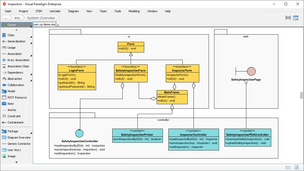
In the world of software engineering, translating abstract requirements into a robust, maintainable codebase is a challenge. This is where the Class Diagram shines as the cornerstone of object-oriented design. The screenshot provided showcases a sophisticated system architecture built within Visual Paradigm, specifically illustrating a classic 3-Tier Architecture pattern.
This tutorial will dissect the diagram to reveal how developers utilize UML (Unified Modeling Language) to structure complex systems, separate concerns, and define clear interactions between the user interface, business logic, and web services.
Understanding the Structural Organization: Folders and Packages
The diagram is visually organized into three distinct “folders” (or packages), which represent the logical grouping of classes. This separation is crucial for maintainability. Instead of a chaotic spaghetti of connections, the architecture enforces boundaries:
- UI Layer (User Interface): Located at the top, this package handles what the user sees and interacts with. It contains the “Form” classes and the “MainFrame.”
- Web Layer: Located on the right, this typically represents the web presentation layer or API entry points.
- Controller Layer: Located at the bottom, this package houses the logic that processes data and coordinates actions between the UI and the backend.
Deconstructing the UI Layer: Boundary Classes
The top package, labeled ui, contains classes that manage the screen state. Notice the use of stereotypes (text in guillemets like <<boundary>>). This is a key UML convention indicating that these classes act as interfaces between the system and the outside world (the user).
Key components include:
- Form (Base Class): A parent class defining a common
initUI()operation. This suggests a standard initialization process for all forms. - LoginForm: A specific boundary class handling user authentication, exposing methods to retrieve input IDs and passwords.
- SafetyInspectionForm & InspectorForm: Domain-specific forms tailored for inspection workflows.
- MainFrame: The central container for the application, likely managing the layout of these forms.
Relationships: Composition vs. Generalization
The lines connecting these boxes are not just connectors; they tell a story about the code’s structure:
- Generalization (Inheritance): The hollow triangle pointing from
LoginFormtoFormindicates inheritance. This meansLoginForm“is a”Formand automatically inherits its properties and methods (likeinitUI()). - Composition (Aggregation): The filled diamond shapes on the lines connecting the
MainFrameto the forms indicate a “whole-part” relationship. This implies strong ownership: if theMainFrameis destroyed, the contained forms are also destroyed.
Deciphering the Controller Layer: The Brain of the Operation
The bottom section of the diagram reveals the Controller classes. In the Model-View-Controller (MVC) pattern, these classes are the “glue.” They accept input from the UI, process it, and update the Model or the View.
Observe the distinct stereotypes used here:
<<control>>: This stereotype identifies classes likeSafetyInspectionPrinter,InspectorController, andSafetyInspectionPDACController. These are responsible for the specific business logic rules of the application.
Key Operations Analyzed:
- InspectorController: Contains methods like
loadInspectorByIDandaddInspector. This class acts as the gateway to the data, likely interacting with a database or service layer to fetch and persist inspection records. - SafetyInspectionPrinter: A specialized controller handling output logic, such as
printInspectionByID. - Dependency Logic: Notice the lines connecting the UI layer to the Controller layer. When a user interacts with a
SafetyInspectionForm, it triggers a call to theSafetyInspectionController. This separation ensures the UI remains “dumb”—it only displays data and captures input, leaving the complex logic to the controllers.
The Web Layer: Bridging to the Outside World
The right-hand folder represents the web context. It contains SafetyInspectionPage, depicted with a circle symbol (often representing a Boundary or Entity boundary in some UML profiles). This suggests a web-based interface or a web service entry point that mirrors the functionality of the desktop application, ensuring cross-platform accessibility.
Why This Architecture Matters
The diagram demonstrates a clean separation of concerns. By strictly defining which classes belong to the UI and which belong to the Controller, the architecture prevents “God Objects” that try to do everything. This leads to code that is easier to test, easier to debug, and easier to scale.
As noted in the context, tools like Visual Paradigm allow developers to visualize these relationships before writing a single line of code, reducing miscommunication by ensuring everyone—from the architect to the junior developer—has a shared understanding of the system’s blueprint.