


Introduction
In today’s rapidly evolving software development landscape, the ability to visualize, communicate, and validate system architecture has become more critical than ever. Unified Modeling Language (UML) stands as the industry-standard notation for modeling software-intensive systems, yet its comprehensive nature—spanning 14 distinct diagram types and over 700 pages of specification—has historically presented a significant learning curve for practitioners.
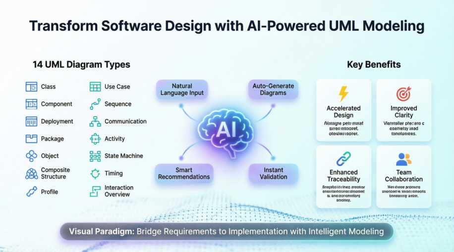
This case study explores how modern UML tooling, particularly Visual Paradigm’s award-winning platform, is transforming the modeling experience by combining comprehensive UML support with cutting-edge artificial intelligence capabilities. Through this examination, we demonstrate how development teams can leverage intelligent modeling tools to accelerate design processes, improve architectural clarity, and bridge the gap between requirements gathering and implementation—ultimately delivering higher-quality software systems with greater efficiency.
The Visual Paradigm UML Tool: Core Capabilities
Create UML models in a snap with an award-winning UML software.
Visual Paradigm provides a comprehensive suite of modeling capabilities designed to support the entire software development lifecycle. The platform enables teams to capture requirements, design system architecture, model behavior, and generate documentation—all within a unified, intuitive environment.
The 14 UML Diagram Types: A Complete Modeling Toolkit
Use Case Diagram
Capture functional requirements with UML use case diagram tool. Each use case in a use case diagram represents a high level business goal that yields a measurable result of business values. (UML) Actors are connected with use cases to represent the roles that interact with the functions.

Class Diagram
The UML modeling tool lets you model the structure of system by modeling its classes, their attributes and operations in a UML class diagram. UML class diagram is a blueprint of the classes (code level) required to build a software system. Programmers implement a software system with the help of both the class diagram and the class specification.

Sequence Diagram
Visualize the interactions between users, systems and sub-systems over time through message passing between objects or roles. If class diagram represents the skeleton of classes by showing their attributes and methods, UML sequence diagram complete the classes by representing the programming logic to be filled in methods’ body.

Communication Diagram
Collaboration between objects in runtime can be modeled in the UML tool, with a UML communication diagram. In a communication diagram, objects, called lifelines, are connected to represent the need of communication during the execution of an interaction. Messages can be added on top of the connectors to list the calls made from and to those lifelines.

Activity Diagram
Use UML activity diagram, a flowchart-based diagram to model the flow of control. Partition actions according to the type of participant involved.

State Machine Diagram
State machine diagram is a critical design model for event-driven systems. Well-designed state machine shows accurately the essential states of objects as well as the triggers of state change, which facilitates the development of error-free state machine.

Component Diagram
Components diagrams are used to model the structure of systems by showing how little parts of the system gear up in forming a bigger part, or forming the entire software systems.

Deployment Diagram
Models the physical deployment of software components with UML deployment diagram. In deployment diagram, hardware components (e.g. web server, mail server, application server) are presented as nodes, with the software components that run inside the hardware components presented as artifacts.

Package Diagram
Arrange and organize model for large-scale project with package diagrams. Package diagram is also good in visualizing structure and dependency between sub-systems or modules.

Object Diagram
View a snapshot of instances of classifiers in UML class diagrams. Similar to class diagrams, object diagrams show the static design of a system from a prototypical perspective.

Composite Structure Diagram
Visualize the internal structure of a class or collaboration with UML composite structure diagram. Model a system from a micro point-of-view using UML composite structure diagram.

Timing Diagram
Timing diagrams model the behavior of objects throughout a given period of time. It is a commonly used UML tool for designing real-time and distributed systems. Just drag to move a time unit back and forth. Have a timing frame updated automatically according to your change.

Interaction Overview Diagram
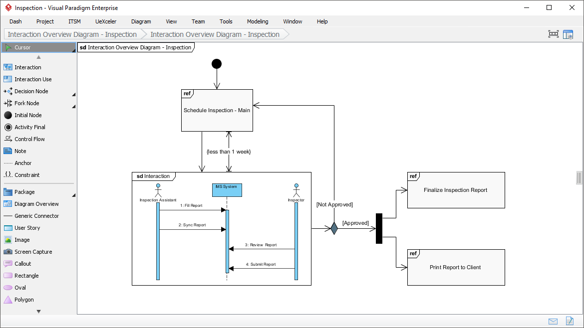
View the sequence of interactions with UML interaction overview diagram. Interaction overview diagram helps represent complex scenario that involve multiple interactions presented as multiple UML sequence diagrams.
Profile Diagram
A visual way to define stereotypes to use in your project. Draw stereotypes, define their tags and their inter-relationships like generalizations and associations. Specify formatting options like background color and icons.

Model Element Referencing: Enhancing Traceability and Documentation

Add diagrams, shapes, model elements as internal references
Make internal links between different kinds of project artifacts. Those references work both in Visual Paradigm and in any document and Web contents generated from your design.
Add business documents as external references
Maintain reference between software design and the business documents to help find out why a design decision was made.
Mark in shape body when have reference added
Glance over a design. The tiny marker that appear in shapes’ body indicates that the shapes have references added.
Reference model element in description
Insert model element references to rich text description. The referenced model elements will be linked and highlighted.
Architecture Meets Intelligence: AI-Powered UML Modeling
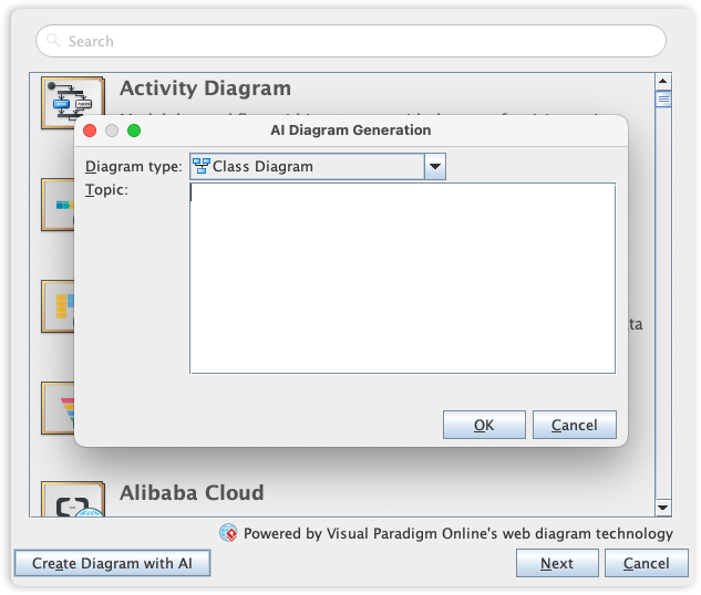
Visual Paradigm’s UML toolset is the industry standard for software modeling, offering the full range of diagrams needed to bridge the gap between requirements and implementation. We are now elevating the entire modeling experience by integrating comprehensive UML support into our AI Diagram Generator, enabling you to visualize system behavior and structure with unprecedented speed.
This capability allows you to instantly generate a wide array of UML diagrams—including Use Case, Class, Sequence, State Machine, Requirement, and Object Diagrams—from a simple textual description. By leveraging AI to interpret your system requirements, the tool automatically maps out the necessary entities, relationships, and interactions, allowing you to move directly to design validation and architectural refinement instead of starting from a blank canvas.
Navigating UML Complexity: A Strategic Learning Approach
Overview of the 14 UML Diagram Types
The Unified Modeling Language is a standardized general-purpose modeling language and nowadays is managed as a de facto industry standard by the Object Management Group (OMG). UML includes a set of graphic notation techniques to create visual models for software-intensive systems.
In UML 2.2 there are 14 types of UML diagrams, which are divided into two categories:
-
7 diagram types represent structural information
-
Another 7 represent general UML diagram types for behavioral modeling, including four that represent different aspects of interactions.
These diagrams can be categorized hierarchically as shown in the following UML diagram map:

Question: UML is Huge and Complex?
UML is a truly a huge topic. UML provides a large volume of diagramming notation grouped into 14 different UML diagram types, each with different UML models, serving different purposes and addressing different aspects of development needs.
-
Each UML diagram of the 14 UML diagram types provides a large set of constructs and notation that cover different needs for most of the software development projects.
-
UML specification has more than 700 pages, and clearly considered as too complex and has a negative impact on the perception and adoption of UML.
-
Typically, users tend to consider and use only a portion of its diagrams/constructs of UML.
Answer: Learn the Most Essential UML Diagrams and Notation
Grady Booch, one of the most important developer of Unified Modeling Language, stated that “For 80% of all software only 20% of UML is needed”.
Mastering 14 UML Types with AI Assistance
With 14 different diagram types and over 700 pages of specifications, UML can be overwhelming. Visual Paradigm’s AI ecosystem simplifies this by helping you select, create, and evolve the right diagrams for your project automatically.
💬 AI Diagram Chatbot
Describe your system logic in natural language and let AI instantly draft the appropriate UML diagram type for you.
🌐 AI WebApps
Follow step-by-step AI-guided workflows to create, refine, and evolve complex diagrams through an intuitive web interface.
⚡ Diagram Generator
Access high-speed automated diagramming tools within the Visual Paradigm ecosystem to maintain 100% modeling accuracy.
📝 OpenDocs
A central knowledge hub to manage your AI-generated diagrams and technical documentation in one integrated environment.
Explore the AI Diagram Generation Ecosystem
What is the UML Survey States?
We could interpret the results of the UML survey by assuming that, if a diagram is:
-
widely used, if it ≥ 60% of the sources
-
scarcely used if it is ≤ 40% of the sources

Make Your UML Learning Plan
Based on the figures collected in the survey, you can have a better idea on how to start your UML learning journey by developing a meaningful UML learning plan. This article also provides you with an image map for quickly visiting to a series of “What is UML Diagram” papers (Just click the boxes of UML diagram in the image map above). Enjoy!
Conclusion
The evolution of UML tooling represents a pivotal shift in how software teams approach system design and architectural communication. Visual Paradigm’s integration of comprehensive UML support with artificial intelligence capabilities demonstrates that powerful modeling need not come at the cost of accessibility or efficiency. By offering all 14 UML diagram types within an intuitive interface, enhancing traceability through sophisticated referencing features, and leveraging AI to accelerate diagram creation from natural language descriptions, modern modeling platforms are removing traditional barriers to UML adoption.
For organizations seeking to improve software quality, enhance team collaboration, and accelerate development cycles, investing in intelligent UML tooling delivers measurable returns. The strategic approach to learning—focusing first on the most widely-used diagram types while leveraging AI assistance for complex scenarios—enables teams to build modeling competency incrementally without being overwhelmed by UML’s full specification. As software systems continue to grow in complexity, the ability to visualize, validate, and communicate architectural decisions through standardized modeling notation becomes not just advantageous, but essential. Visual Paradigm’s AI-enhanced UML ecosystem provides a proven pathway for teams to harness the full power of UML while maintaining the agility required in modern software development environments.
Reference List
- UML Tool Features: Comprehensive overview of Visual Paradigm’s UML modeling capabilities, supporting all 14 UML diagram types for software-intensive system design.
- Import and Export Features: Documentation on Visual Paradigm’s data interchange capabilities, enabling seamless integration with other development tools and documentation systems.
- Object Management Group (OMG): The international standards consortium that manages and evolves the Unified Modeling Language specification as a de facto industry standard.
- AI Diagram Chatbot: Natural language interface for generating UML diagrams through conversational AI, enabling rapid prototyping from textual requirements.
- AI WebApps Platform: Web-based AI-guided workflows for creating, refining, and evolving complex UML diagrams through an intuitive browser interface.
- Visual Paradigm AI Diagram Generation Guide: Step-by-step documentation for leveraging automated diagramming tools to maintain modeling accuracy and efficiency.
- OpenDocs AI Tool: Integrated knowledge management environment for organizing AI-generated diagrams and technical documentation in a centralized repository.
- Best AI Diagram Generator Ecosystem: Comprehensive exploration of Visual Paradigm’s AI-powered modeling ecosystem and its applications across the software development lifecycle.